
Turn on suggestions
Auto-suggest helps you quickly narrow down your search results by suggesting possible matches as you type.
Showing results for
Turn on suggestions
Auto-suggest helps you quickly narrow down your search results by suggesting possible matches as you type.
Showing results for
Community Tip - Learn all about PTC Community Badges. Engage with PTC and see how many you can earn! X
- Community
- Creo+ and Creo Parametric
- 3D Part & Assembly Design
- Re: Assembly Modeling - CREO PARAMETRIC
Options
- Subscribe to RSS Feed
- Mark Topic as New
- Mark Topic as Read
- Float this Topic for Current User
- Bookmark
- Subscribe
- Mute
- Printer Friendly Page
Assembly Modeling - CREO PARAMETRIC
May 01, 2024
02:08 AM
- Mark as New
- Bookmark
- Subscribe
- Mute
- Subscribe to RSS Feed
- Permalink
- Notify Moderator
May 01, 2024
02:08 AM
Assembly Modeling - CREO PARAMETRIC
Hi all,
I was looking at getting some guidance with simple assembly within CREO.
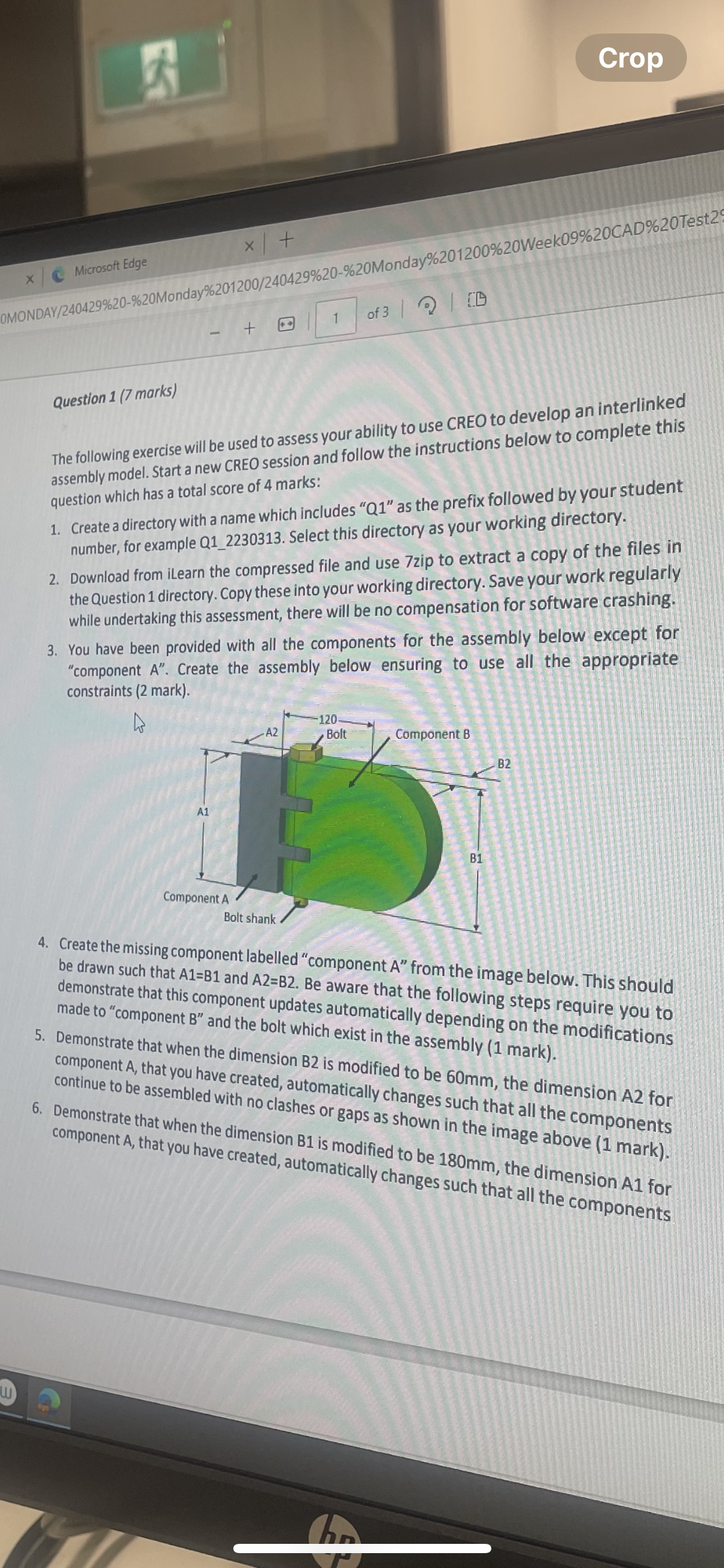
I've been tasked to a create an assembly in which I am given 2 complete parts as well as am required to create a third part for this assembly.
When creating the third part of the assembly is should be drawn that A1 = B1 and A2 = B2, meaning that this component updates automatically depending on the modification made to the first two components which exist in the assembly.
How do I go about this? Do I create a seperate brand new model and then add this to the main assembly. OR should I assemble the first two parts together and then create a new part within this assembly.
This is to made made that no clashes or gaps happen within the main assembly model
Labels:
- Labels:
-
Assembly Design
4 REPLIES 4
May 01, 2024
07:58 AM
- Mark as New
- Bookmark
- Subscribe
- Mute
- Subscribe to RSS Feed
- Permalink
- Notify Moderator
May 01, 2024
07:58 AM
There are multiple ways to do this. You can work on the new part in assembly mode or in part mode. You also can use a multibody part design if you are in Creo 7 or higher. I would build part B as a new part in part mode and use one the following methods. You can build the new part in assembly mode, but I would not pursue that in your case as it has much more opportunity to create unwanted references.
These are two strategies but there are other ways to do it as well.
One option is to write the relations controlling the parts in assembly mode. In this structure part B dimensions drive part A. To do this build the assembly with all required parts. You can then write relations in part A that will use the values of the dims from part B directly. You will need to use the syntax including the session ID of the parts when writing relations. See this link for details on this: About Entering Relations in Assembly (ptc.com)
Another option: Note this technique is not likely taught in your curriculum. In this structure the Notebook file drives parts A & B directly.
I would suggest that you create a new part in part mode and use relations to drive the dimensions controlling the interface geometry. You can easily control the dimensions using a notebook file. About Notebooks (ptc.com)
In the notebook you will create parameters for dimensions B1 and B2. You will then declare the notebook to each part. Once declared you can use the values of B1 and B2 from the notebook in the part model relations. You then write relations in each part that use the B1 & B2 values to control the features in each model. When you need to update the model you can just change the values of B1 and B2 in the notebook file and regenerate the assembly and all parts will update.
========================================
Involute Development, LLC
Consulting Engineers
Specialists in Creo Parametric
Involute Development, LLC
Consulting Engineers
Specialists in Creo Parametric
May 01, 2024
09:14 AM
- Mark as New
- Bookmark
- Subscribe
- Mute
- Subscribe to RSS Feed
- Permalink
- Notify Moderator
May 01, 2024
09:14 AM
Are you a student taking a class in parametric modeling?
May 01, 2024
09:37 AM
- Mark as New
- Bookmark
- Subscribe
- Mute
- Subscribe to RSS Feed
- Permalink
- Notify Moderator
May 01, 2024
09:37 AM
Hmmm, what clues led you to that question?
May 06, 2024
05:05 PM
- Mark as New
- Bookmark
- Subscribe
- Mute
- Subscribe to RSS Feed
- Permalink
- Notify Moderator
May 06, 2024
05:05 PM
Yes layout/notebook is an option, but than you have to change the value in the layout and this was not requested.
Here an other way to archive your goal:
- You have all 3 Model created and assembled
- Change the model tree to display the session ID for each component
- Assume that component B has Session ID 25 and the symbol name D20 is equal to B1
- Pick on component A and the dimension corresponding to A1
- Enter D20:25
- Answer yes on ask to save the relation
Done,
Now the dimension in component B drives the one in A as requested.
Getting extra points: 😎
With an additional relation you may add the model name of ID 25, because you will forget „Which one is 25“ 😉 like model25name=PTC_COMMON_NAME:25
Or if needed add your own parameter in source to display the name and link it into the target.
Good Luck
