
Turn on suggestions
Auto-suggest helps you quickly narrow down your search results by suggesting possible matches as you type.
Showing results for
Turn on suggestions
Auto-suggest helps you quickly narrow down your search results by suggesting possible matches as you type.
Showing results for
Community Tip - Want the oppurtunity to discuss enhancements to PTC products? Join a working group! X
- Community
- Creo+ and Creo Parametric
- 3D Part & Assembly Design
- Re: Reg: creating a pattern in sphere
Options
- Subscribe to RSS Feed
- Mark Topic as New
- Mark Topic as Read
- Float this Topic for Current User
- Bookmark
- Subscribe
- Mute
- Printer Friendly Page
Reg: creating a pattern in sphere
Mar 12, 2013
03:55 AM
- Mark as New
- Bookmark
- Subscribe
- Mute
- Subscribe to RSS Feed
- Permalink
- Notify Moderator
Mar 12, 2013
03:55 AM
Reg: creating a pattern in sphere
I tried to create a golf ball, but after creating a sphere i thought of creating a small hole and then by giving a pattern i thought i might get it, but am not able to create a pattern as it is seen in Golf.. how do i create it??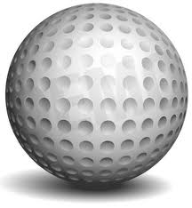
This thread is inactive and closed by the PTC Community Management Team. If you would like to provide a reply and re-open this thread, please notify the moderator and reference the thread. You may also use "Start a topic" button to ask a new question. Please be sure to include what version of the PTC product you are using so another community member knowledgeable about your version may be able to assist.
Labels:
- Labels:
-
General
19 REPLIES 19
Mar 12, 2013
06:34 PM
- Mark as New
- Bookmark
- Subscribe
- Mute
- Subscribe to RSS Feed
- Permalink
- Notify Moderator
Mar 12, 2013
06:34 PM
I have a link soomewhere for this, I'll try and dig it out. I never tried it though.
Mar 13, 2013
12:47 AM
- Mark as New
- Bookmark
- Subscribe
- Mute
- Subscribe to RSS Feed
- Permalink
- Notify Moderator
Mar 13, 2013
12:47 AM
thank you.. i'll be waiting...
Mar 12, 2013
08:26 PM
- Mark as New
- Bookmark
- Subscribe
- Mute
- Subscribe to RSS Feed
- Permalink
- Notify Moderator
Mar 12, 2013
08:26 PM
It kind of depends on which pattern you subscribe to. Wiki has a good guide image: http://en.wikipedia.org/wiki/Golf_ball
Have you considered creating an appropriate texture 
Wouldn't a "fill" pattern work?
Mar 13, 2013
12:38 AM
- Mark as New
- Bookmark
- Subscribe
- Mute
- Subscribe to RSS Feed
- Permalink
- Notify Moderator
Mar 13, 2013
12:38 AM
Texture i have created but i am not sure whether its perfect, but even after creating a texture the coincident points in the texture, i need to make a point in there and have to create a hole, but i tried it.. it didnt come as well..and as for the fill pattern is considered we have to create a hole in the texture only then fill pattern can be applicable. If you know how to create a proper texture ( like in wiki ) in it, help me with the answer i'll give it a try..
Mar 13, 2013
01:56 AM
- Mark as New
- Bookmark
- Subscribe
- Mute
- Subscribe to RSS Feed
- Permalink
- Notify Moderator
Mar 13, 2013
01:56 AM
A texture is an image that can be wrapped onto the surface of the sphere. With a little effort, you can even have the rendering engine mimic the dimple "look". Unfortunely it will not do much to help create the actual dimple feature.
I'll see how close I can come to this. Sounds like an interesting challenge.
Mar 13, 2013
12:16 PM
- Mark as New
- Bookmark
- Subscribe
- Mute
- Subscribe to RSS Feed
- Permalink
- Notify Moderator
Mar 13, 2013
02:49 PM
- Mark as New
- Bookmark
- Subscribe
- Mute
- Subscribe to RSS Feed
- Permalink
- Notify Moderator
Mar 13, 2013
02:49 PM
That model was a lot of effort by someone. I wonder how those pattern tables were generated.
Very nice work, whoever did it (the History interrogation still doesn't work in Creo 2.0 M040).
It does return a username EBOWERMAN.
Mar 13, 2013
06:04 PM
- Mark as New
- Bookmark
- Subscribe
- Mute
- Subscribe to RSS Feed
- Permalink
- Notify Moderator
Mar 13, 2013
06:04 PM
So I started here and it certainly is not complete.
I used the Wiki example on the left as a guide. This creates a 252 hole golf ball.

I am only using this as a skeleton starting point. The dimple sizes are not optimized nor is the size.
Reverse engineering both images shows that it is based on a nested set of 12 pentagons and 20 triangles. With Pro|E (all versions) you can assemble these shapes and they end up locking themselves into the proper form.
From the assembly I drove a sketch back to the pentagon to determine the height of the 5 triangles on the pentagon so I could determine the diameter I ended up with. Again, none of the holes are optimized as yet.
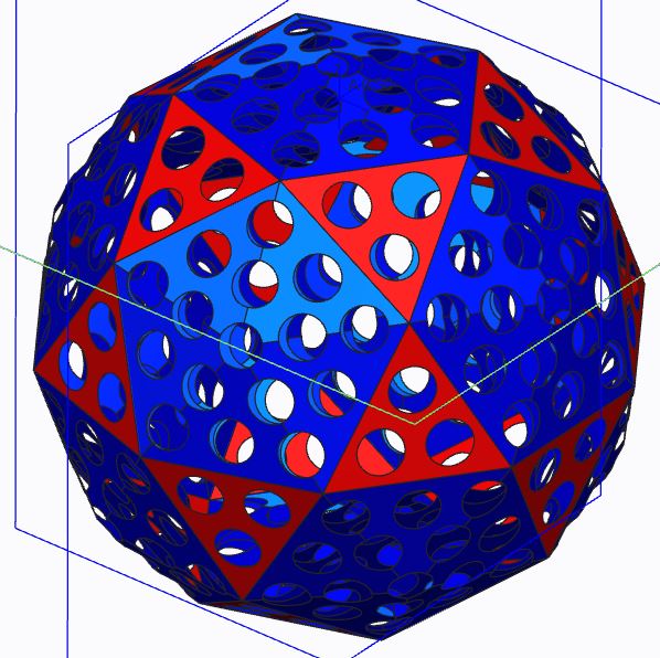
The idea is that you want to be able to define this shape within a part file and not an assembly. Holes, or points, still have to be mapped on a sphere. The dimple sizes are not consistent... you see the full scope of the challenge. And this is not even the definitive standard for golf balls although I do like this one for the challenge at hand.
The next level of subdivisions should determine exactly where the dimples should fall. In that way, points could be added to determine the appropriate location on the sphere.
Mar 14, 2013
12:42 AM
- Mark as New
- Bookmark
- Subscribe
- Mute
- Subscribe to RSS Feed
- Permalink
- Notify Moderator
Mar 14, 2013
12:42 AM
 . i really appreciate the effort you have done here... thanks
Mar 13, 2013
03:49 PM
- Mark as New
- Bookmark
- Subscribe
- Mute
- Subscribe to RSS Feed
- Permalink
- Notify Moderator
Mar 13, 2013
03:49 PM
The pattern of the dimples in the picture that you supplied actually looks pretty simple when looking at it through a spherical coordinate lens. My first approach would be to use another program (Python, MATLAB, Excel, etc.) to calculate the locations of all the points of the dimples and save the points in a separate file. I would then have pro/e load those points with the Offset Coordinate System Datum Point Tool (I think... I have never tried this). I would then make one dimple feature, and use the point pattern tool to fill the rest of the dimples.
I think this would work to make a ball in the image that you attached. You would quickly run into logistical issues if trying to replicate the ball the Frank attached. You could probably still use the method, but you would likely have to break it into smaller pieces.
When I find some time, I might have to give this a shot. I will let you guys know how it goes.
Mar 14, 2013
02:28 AM
- Mark as New
- Bookmark
- Subscribe
- Mute
- Subscribe to RSS Feed
- Permalink
- Notify Moderator
Mar 14, 2013
02:28 AM
Hi All,
here is my model of golf ball: GOLF - Gentleman Only, Ladies Forbidden?
Vladimir
Best Regards,
Vladimir Palffy
Vladimir Palffy
Mar 14, 2013
05:10 PM
- Mark as New
- Bookmark
- Subscribe
- Mute
- Subscribe to RSS Feed
- Permalink
- Notify Moderator
Mar 14, 2013
05:10 PM
http://communities.ptc.com/message/165911#165911
Scroll down and you`ll see golf ball with explanation. I`ll see if i can find my old model from this post tommorow.
Mar 15, 2013
04:21 PM
- Mark as New
- Bookmark
- Subscribe
- Mute
- Subscribe to RSS Feed
- Permalink
- Notify Moderator
Mar 15, 2013
04:21 PM
Mani, you have unintentionally started a surprisingly challenging discussion and quite a few off-shoots.
And since you started it, I should follow up. I spent most of the week trying to "understand" the problem rather than just making due. Between the challenge itself and making Creo do what it should really did provide a lot of insight and even frustration.
This is what I ended up with: 260 dimples on a 1.68" sphere. This model is attached as a STEP file.
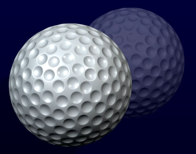
I ended up using 3 levels to manage the point plotting onto the face for patterning. This technique could be used for any pattern, but I choose the Wiki version with a few extra holes at the centers of the resulting hex pattern.
The 1st level was as discussed before, a modified dodec/icosahedron (32 faces).
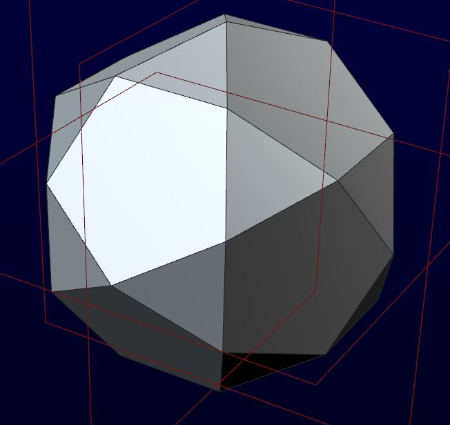
I was finally able to generate this shape with a comprehensive sketch that controls planes from which the "fill" patterns were created.
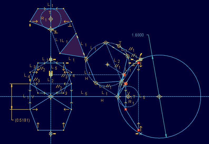
Next, I needed to stellate one of the pentagons. Through the sketch, I was able to determine the of the center on the bounding sphere. Then 2 key sketches were created to determine the centers. These odd sketches will determine the "centers" of the dimples at the points of the pie shaped pieces.
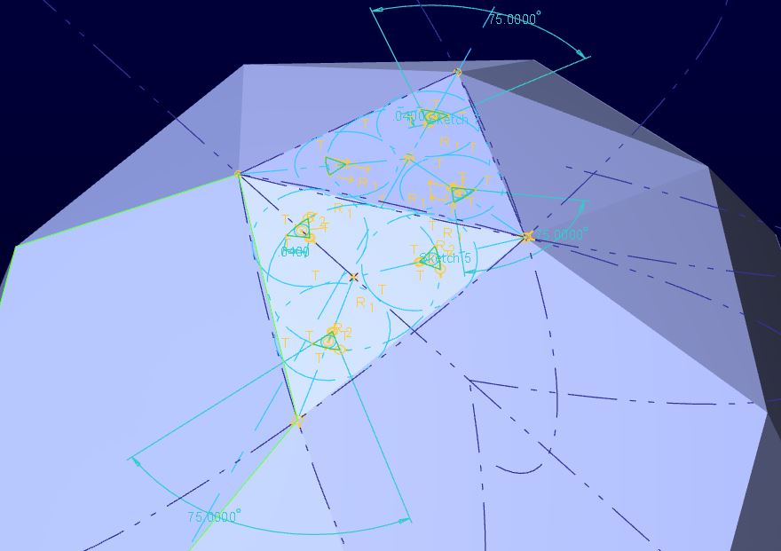
A surface sphere of the final size was created. These sketches were used to create Offsets. This provides Vertexes to use for patterning later on. The offsets were patterned on a hemisphere.
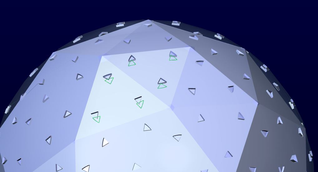
Now, 95% of the work is done. I have vertex locations on the sphere surface. Next a solid sphere is created and a 1st dimple is revolved from the solid face.
Now, I -thought- I could make datum points on the surface using the "darts" I created. But patterning to those points does not maintain a surface normal. All the axes of the pattern became unidirectional without options. Even if I tried to orient the points, no joy. The answer was to map the points onto a sketch in the pattern command. This was easy enough. Now you have the options of mapping to surface normals. remember to choose the Origin as well.
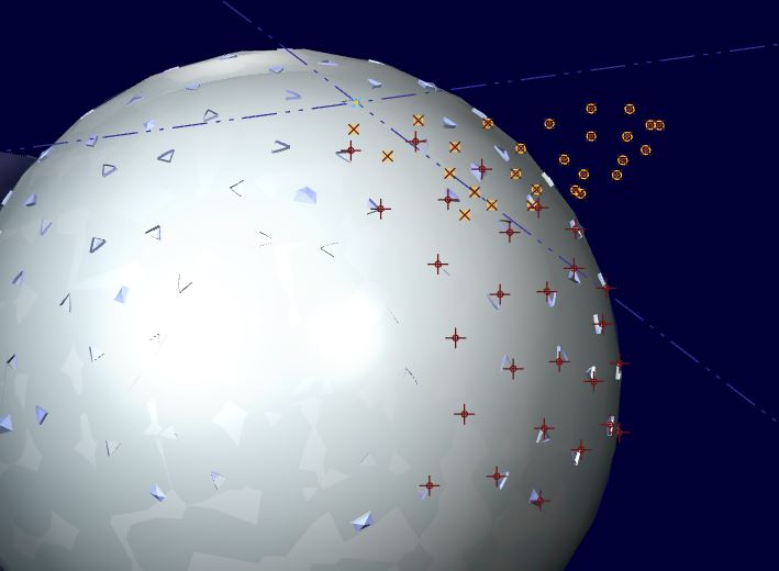
Now I am able to modify the 2 simple sketches above and optimize the distribution of the dimples by tweaking the sketch constraints. You will notice I used one size dimple. Even greater optimization could be done if you separated the dimple creation in 2 steps.
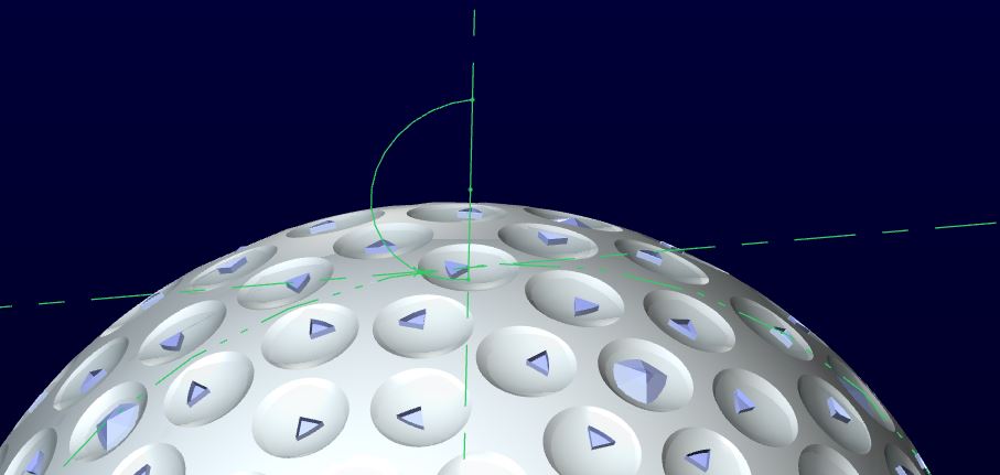
From here, this patterns were copied, pasted w/ 180 degree rotation, grouped, and rotated about an axis 5 times. And last, the fillets were added.
To clean up the file, I hid all the reference geometry and also the 260 axes that were created from the dimple cuts and saved the layer status.
And the end result is attached
Mar 15, 2013
06:19 PM
- Mark as New
- Bookmark
- Subscribe
- Mute
- Subscribe to RSS Feed
- Permalink
- Notify Moderator
Mar 15, 2013
06:19 PM

Very impressive work. Just creating the modified dodec/icosahedron requires a bit of thought and foresight, not to mention the path you took to complete the other two steps. Awesome model!
A ball with some dimples... How hard can that be? Oh... Wait...
Mar 16, 2013
06:28 PM
- Mark as New
- Bookmark
- Subscribe
- Mute
- Subscribe to RSS Feed
- Permalink
- Notify Moderator
Mar 16, 2013
06:28 PM
Thanks Kyle! 
Mar 16, 2013
06:27 PM
- Mark as New
- Bookmark
- Subscribe
- Mute
- Subscribe to RSS Feed
- Permalink
- Notify Moderator
Mar 16, 2013
06:27 PM
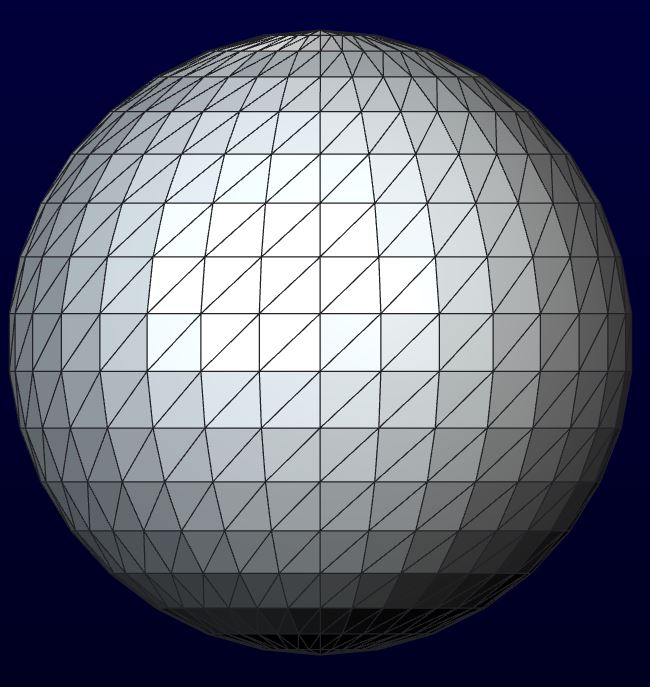
As an aside, there is one way to quickly create vertexes for a spherical surface. You can export a half-sphere surface to VRML (.wrl) and open (import) it. This creates a facet feature (whatever that is). If the export went well, it creates a nicely segmented sphere... although on a square pattern. This does provide many vertices for patterning or for generating a more complex patterning sketch.
The other observation that this exercise presents is the spherical spiral that could be used for patterning with 3D datum curves, even if these curves were generated from equations.
I have spend years working with VRML files. With some advanced editing techniques, they can be very useful in capturing large datasets and even manual manipulation of the data. Point files should be easy to create from VRML files. These are essentially point clouds with polygon definitions.
coord DEF FaceC Coordinate {
point [
0 -0.21335975 0,
0 -0.21286241 -0.014560042,
0 -0.2113727 -0.029052266,
0 -0.20889722 -0.043409362,
0 -0.20717408 -0.05047996,
-0.012087606 -0.20729499 -0.049041558,
-0.023472902 -0.20729499 -0.044723812,
-0.033493964 -0.20729499 -0.037806884,
...
...and polygon connections using the point numbers as reference for connectivity:
normalPerVertex TRUE
coordIndex [
5, 25, 24, -1,5, 24, 23, -1,5, 23, 22, -1,
5, 22, 21, -1,4, 5, 21, -1,26, 25, 5, -1,
26, 46, 45, -1,26, 45, 44, -1,26, 44, 43, -1,
25, 26, 43, -1,47, 46, 26, -1,47, 67, 66, -1,
47, 66, 65, -1,47, 65, 64, -1,47, 64, 63, -1,
46, 47, 63, -1,68, 67, 47, -1,68, 88, 87, -1,
68, 87, 86, -1,68, 86, 85, -1,67, 68, 85, -1,
89, 88, 68, -1,89, 109, 108, -1,89, 108, 107, -1,
89, 107, 106, -1,89, 106, 105, -1,88, 89, 105, -1,
110, 109, 89, -1,110, 130, 129, -1,110, 129, 128, -1,
110, 128, 127, -1,109, 110, 127, -1,131, 151, 150, -1,
...
...and they even contain face normal definisions!
normal DEF FaceN Normal {
vector [
0 -1 0,
0 -0.997 -0.068,
0 -0.99 -0.136,
0 -0.979 -0.203,
0 -0.971 -0.236,
-0.056 -0.971 -0.229,
-0.11 -0.971 -0.209,
-0.156 -0.971 -0.177,
-0.194 -0.971 -0.134,
-0.221 -0.971 -0.083,
-0.235 -0.971 -0.028,
...
This could simplify the original request if an acceptable pattern can be visualized within this model.
I have attached the hemisphere_prt.wrl file for your convenience.
Mar 16, 2013
02:16 PM
- Mark as New
- Bookmark
- Subscribe
- Mute
- Subscribe to RSS Feed
- Permalink
- Notify Moderator
Mar 16, 2013
02:16 PM
Spherically pattern - new pattern for Spherically shape
What do you think? It is good idea for new feature in Creo? - Vote here
Best Regards,
Vladimir Palffy
Vladimir Palffy
Mar 16, 2013
03:38 PM
- Mark as New
- Bookmark
- Subscribe
- Mute
- Subscribe to RSS Feed
- Permalink
- Notify Moderator
Mar 16, 2013
03:38 PM
Ideas should be a bit more descriptive, so I added a comment. Maybe you could add it to the idea.
Mar 21, 2013
04:48 AM
- Mark as New
- Bookmark
- Subscribe
- Mute
- Subscribe to RSS Feed
- Permalink
- Notify Moderator
Mar 21, 2013
04:48 AM
Trick is to make half sphere not whole sphere and then project pattern on to it. Fill Pattern type must be circular. First dent u create in center of halfsphere surface. when you complete halfsphere you just mirror it.
Now comes problem with distance between pattern items on 1 halfsphere and other. You must use a bit of math in relations to achive nearly perfect ball.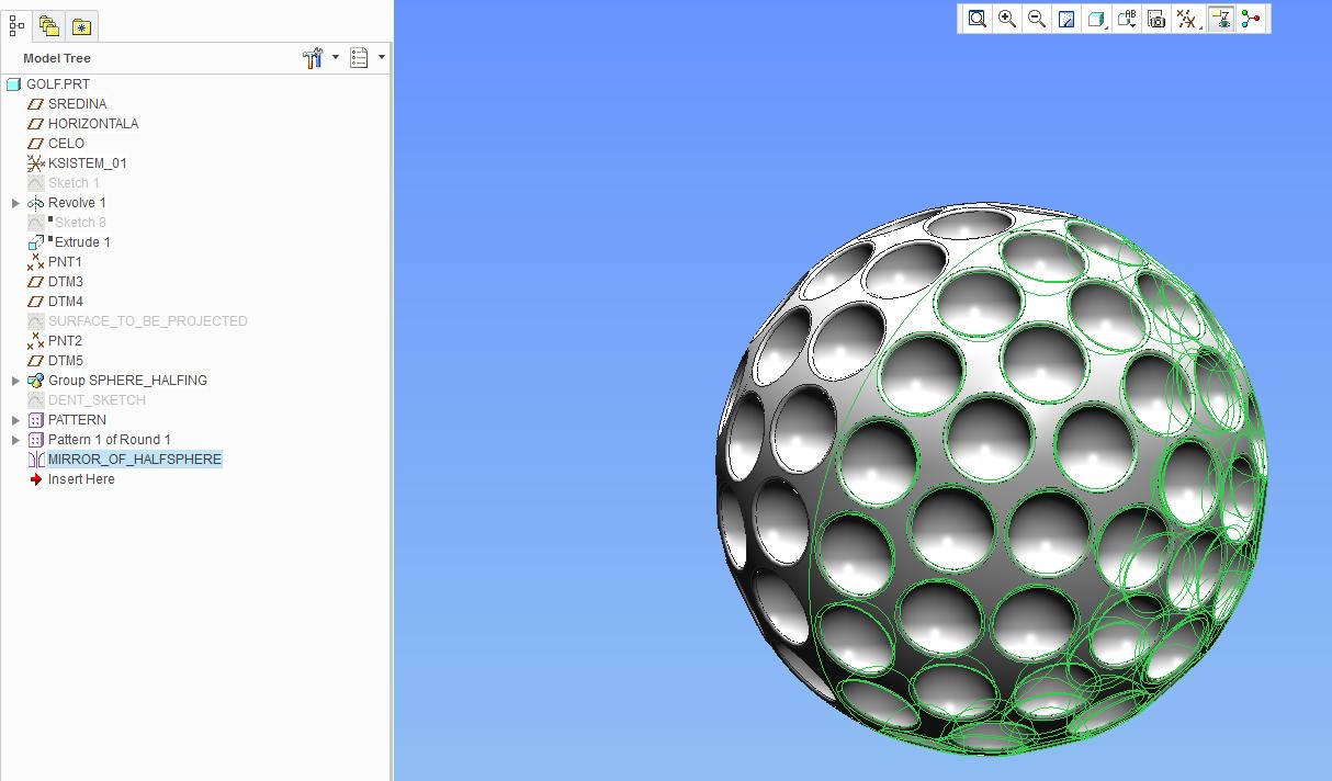
Here is the model:
