
Turn on suggestions
Auto-suggest helps you quickly narrow down your search results by suggesting possible matches as you type.
Showing results for
Turn on suggestions
Auto-suggest helps you quickly narrow down your search results by suggesting possible matches as you type.
Showing results for
Community Tip - Your Friends List is a way to easily have access to the community members that you interact with the most! X
- Community
- Creo+ and Creo Parametric
- 3D Part & Assembly Design
- Re: Importing Iges/Step files into Creo Parametric...
Options
- Subscribe to RSS Feed
- Mark Topic as New
- Mark Topic as Read
- Float this Topic for Current User
- Bookmark
- Subscribe
- Mute
- Printer Friendly Page
Importing Iges/Step files into Creo Parametric 2.0 for Editing
Feb 07, 2013
10:17 AM
- Mark as New
- Bookmark
- Subscribe
- Mute
- Subscribe to RSS Feed
- Permalink
- Notify Moderator
Feb 07, 2013
10:17 AM
Importing Iges/Step files into Creo Parametric 2.0 for Editing
Good Morning,
I have recently started using Creo Parametric 2.0. I am trying to import iges and step files into Creo and edit the features. Everytime I open the iges or step file in Creo I am unable to measure between two surfaces much less change any features on any of the parts within the assembly. Is there another way to import these files for editing purposes?
Thanks,
Robert
This thread is inactive and closed by the PTC Community Management Team. If you would like to provide a reply and re-open this thread, please notify the moderator and reference the thread. You may also use "Start a topic" button to ask a new question. Please be sure to include what version of the PTC product you are using so another community member knowledgeable about your version may be able to assist.
Labels:
- Labels:
-
Data Exchange
34 REPLIES 34
Feb 07, 2013
10:45 AM
- Mark as New
- Bookmark
- Subscribe
- Mute
- Subscribe to RSS Feed
- Permalink
- Notify Moderator
Feb 07, 2013
10:45 AM
Editing has always been a problem with imported files... PTC believes it is protecting integrity. It has gotten easier. You are probably dealing with an ATB issue (the associated topology bus).
Each different file type behaves differently. Measuring however should not be an issue. The import data doctor may be able to help.
You can try making the main feature "independent" by right clicking and selecting Associative Topology Bus.
You can also try changing the Import Profile Editor under the Tools tab.
Feb 07, 2013
10:53 AM
- Mark as New
- Bookmark
- Subscribe
- Mute
- Subscribe to RSS Feed
- Permalink
- Notify Moderator
Feb 07, 2013
10:53 AM
I'm still using WF5, but for what's it worth, PTC is advertising Creo 2.0 as being able to take files from other Cad tools and edit them. Here's a link to a 2 minute video that I just got in an email from our VAR...
Feb 07, 2013
11:02 AM
- Mark as New
- Bookmark
- Subscribe
- Mute
- Subscribe to RSS Feed
- Permalink
- Notify Moderator
Feb 07, 2013
11:02 AM
That is more an add for the flexible modeling extension, but yes, I can make changes to imported files with basic Creo these days but it is limited.
Feb 07, 2013
12:22 PM
- Mark as New
- Bookmark
- Subscribe
- Mute
- Subscribe to RSS Feed
- Permalink
- Notify Moderator
Feb 07, 2013
12:22 PM
Hi Bob,
Antonius is on the mark. I've seen a lot of confusion with the "AnyData" sales pitch. I think the confusion comes from the term "Edit". Many of us have the perception that "Edit" means change a feature based on it's defintion. PTC's flexible modeling extension can recognise some things like holes and patterns and adjust a diameter, or change the pattern spacing.
It does not have a model tree and you won't have access to the original dimensions used to create the features.
Feb 07, 2013
12:29 PM
- Mark as New
- Bookmark
- Subscribe
- Mute
- Subscribe to RSS Feed
- Permalink
- Notify Moderator
Feb 07, 2013
12:29 PM
Thanks for the clarification regarding the use of the flexible modeling extension tool.
Jan 10, 2014
05:31 PM
- Mark as New
- Bookmark
- Subscribe
- Mute
- Subscribe to RSS Feed
- Permalink
- Notify Moderator
Jan 10, 2014
05:31 PM
So why do companies allow you to use these files but you have no way to edit the part in Creo 2.0? Just for viewing purposes?
I'm trying to import just the hole into a block I've made but I cant even use it. Looks like saving time isn't an option for me. Ughhh
Jan 10, 2014
08:19 PM
- Mark as New
- Bookmark
- Subscribe
- Mute
- Subscribe to RSS Feed
- Permalink
- Notify Moderator
Jan 10, 2014
08:19 PM
In part it depends on what you mean by editting.
PTCs parametric modeler is a procedural modeler that also allows changing named values. Procedural means that there is an order to the operations needed to build the model.
Step and IGES are boundary models. There are no operations in the models, and so there are no procedures.
In particular, Step and IGES don't store the 2D geometry that was used to create the 3D model. There is nothing to 'edit' in the Pro/E parametric sense.
The reason you can use them, even if changing them is difficult, is because most of the time you would not change them. Standard hardware, an engine, and electrical components; are all items that are useful to design, but don't need much change. That said, you can use imported models and add and subtract material.
You can probably borrow the hole by copying the surface geometry and pasting it where needed.
Jan 11, 2014
06:24 AM
- Mark as New
- Bookmark
- Subscribe
- Mute
- Subscribe to RSS Feed
- Permalink
- Notify Moderator
Jan 11, 2014
06:24 AM
In Creo there is a feature recognition tool which creates parametric features from geometry. You have to activate it by frt_enabled yes. Though very limited it may help in some cases.
Reinhard
Jan 11, 2014
10:54 AM
- Mark as New
- Bookmark
- Subscribe
- Mute
- Subscribe to RSS Feed
- Permalink
- Notify Moderator
Jan 11, 2014
10:54 AM
Aside from the time, it doesn't hurt to try. According to the following it reqiures a restart with the configuration option enabled.
Jan 12, 2014
04:59 PM
- Mark as New
- Bookmark
- Subscribe
- Mute
- Subscribe to RSS Feed
- Permalink
- Notify Moderator
Jan 12, 2014
04:59 PM
This is worth reading as well:
http://www.cadhelpcenter.com/2010/08/06/feature-recognition-in-proengineer-wildfire-5-0/
Jan 13, 2014
01:29 PM
- Mark as New
- Bookmark
- Subscribe
- Mute
- Subscribe to RSS Feed
- Permalink
- Notify Moderator
Jan 13, 2014
01:29 PM
Feature recognition would be a best way to go. The hole would get recognized as a sketched hole.
Too bad frt_enabled always switches to no in the later versions of Creo Parametric 2.0.
Jan 15, 2014
09:07 AM
- Mark as New
- Bookmark
- Subscribe
- Mute
- Subscribe to RSS Feed
- Permalink
- Notify Moderator
Jan 15, 2014
09:07 AM
How would I use feature recognition tool in my case?
Jan 15, 2014
01:46 PM
- Mark as New
- Bookmark
- Subscribe
- Mute
- Subscribe to RSS Feed
- Permalink
- Notify Moderator
Jan 15, 2014
01:46 PM
hi Kaci,
Model tab --> Get Data dropdown --> Feature Recognition fly out --> search hole
frt_enabled has to be set to yes, else Feature Recogniton is greyed out
The model has to be a solid, so all the stuff you've done in IDD was just for the sake of practicing.
Could you tell what are you trying to change on that hole? It's dimensions or just it's position?
Jan 15, 2014
02:33 PM
- Mark as New
- Bookmark
- Subscribe
- Mute
- Subscribe to RSS Feed
- Permalink
- Notify Moderator
Jan 15, 2014
02:33 PM
I guess you need the flexible model extension to get this option.
I have an IGES import and after seting the FRT_ENABLED to YES, I still don't see the Feature Recognition choice.
Jan 15, 2014
03:06 PM
- Mark as New
- Bookmark
- Subscribe
- Mute
- Subscribe to RSS Feed
- Permalink
- Notify Moderator
Jan 15, 2014
03:06 PM
It used to be just a plugin for Pro/E back in the days of WF4.
Hah, said it like the days of WF4 are already over for some time now. 
http://www.ptc.com/products/proe/frt/index.htm
Then in WF5 it was added to Pro/E natively. The thing with Creo Parametric 2.0 is that feature recognition is almost always greyed out. Not sure why, I've had a computer where it worked no problem, but then got a new one where it won't work at all.
Jan 15, 2014
03:21 PM
- Mark as New
- Bookmark
- Subscribe
- Mute
- Subscribe to RSS Feed
- Permalink
- Notify Moderator
Jan 15, 2014
03:21 PM
I wonder if I need to do something on the install of Creo. I see nothing. When I use the command find tool, it says Feature Recognition, but doesn't highlight anything or do anything.
Nothing shows up in the Get Data dropdown other than the normal 4 options.
Jan 15, 2014
03:32 PM
- Mark as New
- Bookmark
- Subscribe
- Mute
- Subscribe to RSS Feed
- Permalink
- Notify Moderator
Jan 15, 2014
03:32 PM
Duh... okay. I need to add it in my config.pro -before- booting up Creo. now it is there. You cannot just enable it from the option config editor.
You know, they have a lot of space for this command in the short description. They could at least put that little tit-bit of information in there, don't ya think!?
Jan 16, 2014
11:59 AM
- Mark as New
- Bookmark
- Subscribe
- Mute
- Subscribe to RSS Feed
- Permalink
- Notify Moderator
Jan 16, 2014
11:59 AM
Yeah, even names of some configs aren't very descriptive, but let's better not change those.
So does the feature recognition tool work for you, Tom? Or is it greyed out?
Jan 16, 2014
12:05 PM
- Mark as New
- Bookmark
- Subscribe
- Mute
- Subscribe to RSS Feed
- Permalink
- Notify Moderator
Jan 16, 2014
12:05 PM
It is available with an appropriate import file. It works with surface models and solid models (IGS, STP). Creo M040.
Jan 16, 2014
12:32 PM
- Mark as New
- Bookmark
- Subscribe
- Mute
- Subscribe to RSS Feed
- Permalink
- Notify Moderator
Jan 16, 2014
12:32 PM
Duh, M070 and greyed out here.
Guess I'm doing something wrong.
Jan 13, 2014
10:51 AM
- Mark as New
- Bookmark
- Subscribe
- Mute
- Subscribe to RSS Feed
- Permalink
- Notify Moderator
Jan 13, 2014
10:51 AM
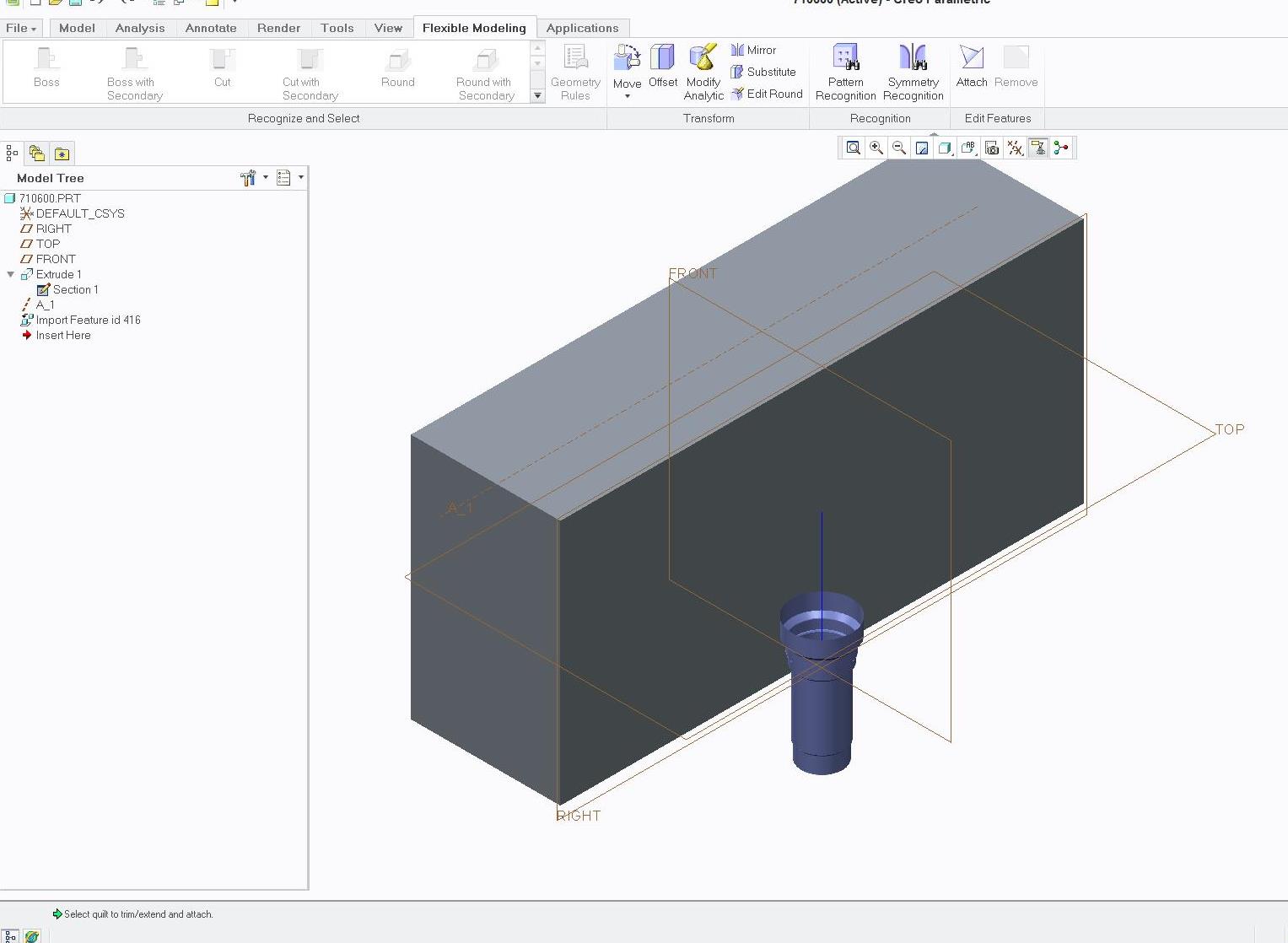
Okay, I was able to figure out how to remove the excess material around the hole using Import Data Doctor and then made a axis line. Now I need to figure out how to attached the hole to the axis line. Or is there an easy way without the axis?
Jan 13, 2014
12:06 PM
- Mark as New
- Bookmark
- Subscribe
- Mute
- Subscribe to RSS Feed
- Permalink
- Notify Moderator
Jan 13, 2014
12:06 PM
If you are set on using that hole geometry without redrawing it, what I think I would do is keep it a seperate part. draw a surface over the top of it, merge it, solidify it, add center axis and a couple planes. Then start an assembly, assemble or create your new block, then assenble in your hole and cut it out. You might even be to that in part mode, too.
Jan 13, 2014
01:14 PM
- Mark as New
- Bookmark
- Subscribe
- Mute
- Subscribe to RSS Feed
- Permalink
- Notify Moderator
Jan 13, 2014
01:14 PM
I think I would opt to make a sketch through the part and save it.
Then recall the sketch where I wanted to use it in a revolve.
Then delete the import feature.
That import will have vertices on which you can make an accurate sketch, and when you remove the references one by one, the sketch's solver will apply dimensions, or you can apply your own. Just remember to remove all dependencies from the import feature. Also remember to make sure the sketch can be imported with only the X-Y location being free but otherwise fully locked so you can move it to where you want it without it distorting.
However, as Matt says, if this is a tool or common library cut, a little extra effort may be worth it. Merge is one means to do this while saving it as a library part (or tool).
Jan 14, 2014
01:48 PM
- Mark as New
- Bookmark
- Subscribe
- Mute
- Subscribe to RSS Feed
- Permalink
- Notify Moderator
Jan 14, 2014
01:48 PM
How do you save a seperate sketch in part mode? When I draw the sketch over the part and finish I try to delete import feature but it also deletes my new revolved feature.
Jan 14, 2014
02:51 PM
- Mark as New
- Bookmark
- Subscribe
- Mute
- Subscribe to RSS Feed
- Permalink
- Notify Moderator
Jan 14, 2014
02:51 PM
When you are in the sketch, you simply save it. It will make a filename.sec file.
Jan 15, 2014
09:55 AM
- Mark as New
- Bookmark
- Subscribe
- Mute
- Subscribe to RSS Feed
- Permalink
- Notify Moderator
Jan 15, 2014
09:55 AM
Ok I have it saved. How do I insert the sketch into my block drawing? I tried Model Tab > Get Data > Import but I cant find my saved sketch.
Jan 15, 2014
02:08 PM
- Mark as New
- Bookmark
- Subscribe
- Mute
- Subscribe to RSS Feed
- Permalink
- Notify Moderator
Jan 15, 2014
02:08 PM
It should be in your working folder with a .sec extension. Note where the section is saved in the save dialog.
Jan 16, 2014
10:21 AM
- Mark as New
- Bookmark
- Subscribe
- Mute
- Subscribe to RSS Feed
- Permalink
- Notify Moderator
Jan 16, 2014
10:21 AM
All it lets me view after selecting All Files drop down is .dwg and .stp files. I checked to see if its in there and it is, just cant import it.
Jan 16, 2014
10:55 AM
- Mark as New
- Bookmark
- Subscribe
- Mute
- Subscribe to RSS Feed
- Permalink
- Notify Moderator
Jan 16, 2014
10:55 AM
You can open .sec files in Sketcher
