Turn on suggestions
Auto-suggest helps you quickly narrow down your search results by suggesting possible matches as you type.
Showing results for
Turn on suggestions
Auto-suggest helps you quickly narrow down your search results by suggesting possible matches as you type.
Showing results for
Community Tip - Stay updated on what is happening on the PTC Community by subscribing to PTC Community Announcements. X
Options
- Subscribe to RSS Feed
- Mark Topic as New
- Mark Topic as Read
- Float this Topic for Current User
- Bookmark
- Subscribe
- Mute
- Printer Friendly Page
how to make curve with equation
Oct 02, 2014
04:19 PM
- Mark as New
- Bookmark
- Subscribe
- Mute
- Subscribe to RSS Feed
- Permalink
- Notify Moderator
Oct 02, 2014
04:19 PM
how to make curve with equation
Hi Team,
I would like to make axial fan flow curve using equation. application is air conditions inlet fan airflow design.
please help out make curve with equation, equation should be dependent on radius. If I change radius the curve should be updated as per that.
thanks,
Madhu
18 REPLIES 18
Oct 02, 2014
05:49 PM
- Mark as New
- Bookmark
- Subscribe
- Mute
- Subscribe to RSS Feed
- Permalink
- Notify Moderator
Oct 02, 2014
05:49 PM
Please post a worksheet with the equation.
Oct 03, 2014
08:18 AM
- Mark as New
- Bookmark
- Subscribe
- Mute
- Subscribe to RSS Feed
- Permalink
- Notify Moderator
Oct 03, 2014
08:18 AM
here is my question how, where to start. I donot know anything about creating curve with equation.
could you please tell me the procedure from start to end.
Oct 03, 2014
08:48 AM
- Mark as New
- Bookmark
- Subscribe
- Mute
- Subscribe to RSS Feed
- Permalink
- Notify Moderator
Oct 03, 2014
08:48 AM
Madhu Sonnathi wrote:
here is my question how, where to start.
Where?
Chose "Use advanced editor" at the upper right and then you get the option at the end of your post to attach a worksheet.
Another question, as I see that so far you had only posted in the Creo section: Are you sure you have a problem with the program Mathcad?
Oct 03, 2014
08:59 AM
- Mark as New
- Bookmark
- Subscribe
- Mute
- Subscribe to RSS Feed
- Permalink
- Notify Moderator
Oct 03, 2014
08:59 AM
I got u about atttachment of files.
I've not created any worksheet, I struck at begining so far I didnot used any equations for modeling. now I got a chance to work with equations need to learn & explore.
share me any example of creation of involute profiles.
please help me out.
Oct 03, 2014
09:04 AM
- Mark as New
- Bookmark
- Subscribe
- Mute
- Subscribe to RSS Feed
- Permalink
- Notify Moderator
Oct 03, 2014
09:04 AM
A much to general question, I guess.
Just take a look at the help pages. Where you find them is dependent on the version of Mathcad you are using.
If you have any specific question, come back here and ask.
Oct 03, 2014
11:09 AM
- Mark as New
- Bookmark
- Subscribe
- Mute
- Subscribe to RSS Feed
- Permalink
- Notify Moderator
Oct 03, 2014
11:09 AM
You should look through the tutorials. The only way we could answer such a general question is to repeat what they say.
Oct 03, 2014
11:45 AM
- Mark as New
- Bookmark
- Subscribe
- Mute
- Subscribe to RSS Feed
- Permalink
- Notify Moderator
Oct 03, 2014
11:45 AM
Richard Jackson wrote:
You should look through the tutorials. The only way we could answer such a general question is to repeat what they say.
I am still not sure about Madhu's question. He is asking quite specific for involute profiles which rather suggests its not a Mathcad question anyway. Of course I may be wrong about that.
Oct 06, 2014
06:32 AM
- Mark as New
- Bookmark
- Subscribe
- Mute
- Subscribe to RSS Feed
- Permalink
- Notify Moderator
Oct 06, 2014
06:32 AM
Do you have a pdf or other document that shows the basic form of the equation that you want to write.
A general question such as the one you have asked can never get a simple answer.
It is far better to have a specific question that we can focus on & hopefully give you helpful advice.
regards
Andy
Oct 06, 2014
08:55 AM
- Mark as New
- Bookmark
- Subscribe
- Mute
- Subscribe to RSS Feed
- Permalink
- Notify Moderator
Oct 06, 2014
08:55 AM
This is a very complex subject.
Attached is a very simplistic development of a generic curve. And a discussion of the subject.
Oct 09, 2014
07:25 AM
- Mark as New
- Bookmark
- Subscribe
- Mute
- Subscribe to RSS Feed
- Permalink
- Notify Moderator
Oct 09, 2014
07:25 AM
Not sure if this exactly what you are looking for.
You can see some great examples done by Dr J Alan Adams
http://www.usna.edu/Users/mecheng/adams/indexf.html
Links to the lectures will then allow you download the Mathcad worksheets.
Note the worksheets are all in Mathcad 2001i, if you want to use them in Mathcad Prime you will need to convert them.
I took the worksheet a step further.
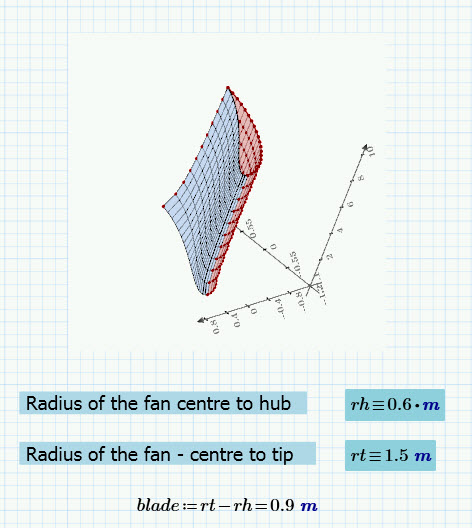
We can take the 2D profiles of the blade calculated (I modified Alan's worksheets on Axial flow machines)
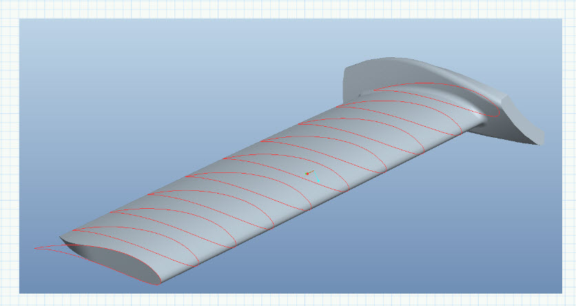
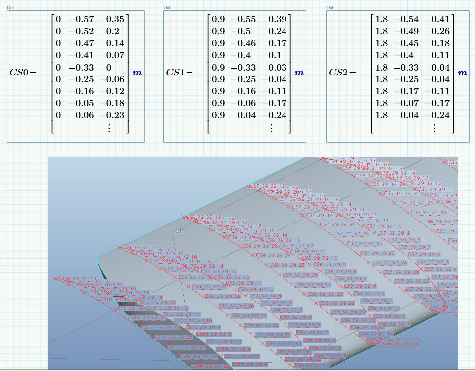
Generate the XYZ coordinates and use the curves at specified intervals along the blade to recreate the solid part in CAD. (Creo parametric in this case)
In this example the centre-tip and centre-hub radii are varibles in Mathcad. (they can be associated with parameters in CREO)
Thomas
Oct 10, 2014
03:24 AM
- Mark as New
- Bookmark
- Subscribe
- Mute
- Subscribe to RSS Feed
- Permalink
- Notify Moderator
Oct 10, 2014
03:24 AM
Thomas,
Thank you for providing this information.
Jan 17, 2015
12:19 PM
- Mark as New
- Bookmark
- Subscribe
- Mute
- Subscribe to RSS Feed
- Permalink
- Notify Moderator
Jan 17, 2015
12:19 PM
Dear Thomas,
Please, I have a very urgent question. I am designing the blade of the last stage of a low pressure axial steam turbine. The blade is supposed to be twisted and the design is supposed to be in the 3D space. That means, the cascade geometry changes from the Hub cross section, through the Medium cross section to the blade tip cross-section. At these 3 sections, the blade angles are different and the 3D model has to reflect that. I have done all the basic calculations and have all my entry and exit angles for the rotor and stator.
I have to create a 3D model now of the blade based on my calculations in order to carry out a CFD simulation with ANSYS. I have spent almost 2 weeks now reading over various books and blogs but I can't find any information on how to create this 3D profile. I have tried starting with basic NACA profiles and to further work from there but my models don't match the physics of my calculations at all. I have used the so-called Pritchard's eleven geometric parameters method to create the cascade profile but I just can't get any sensible model in Creo parametric.
I have read of Bezier curves and how they could be used to create cascade profiles. I know how to create the cascade profiles in Creo parametric but I need the right coordinates that would match my physics i.e the entry and exit angles that I have obtained from my initial calculations.
Please, I need help. If you can explain to me how you modified Dr. Alan's worksheet for axial flow machines in order to obtain the coordinates and hence create the model that you have attached, I would be very very grateful.
Thanks in advance for your help. Please let me know if you need further information from me in order to adequately help me.
Thanks
Jan 19, 2015
07:01 AM
- Mark as New
- Bookmark
- Subscribe
- Mute
- Subscribe to RSS Feed
- Permalink
- Notify Moderator
Jan 19, 2015
07:01 AM
Hi Jama,
Please post your question in "Creo" forum too, maybe that will help get you there: http://communities.ptc.com/community/post!input.jspa?containerType=14&container=2023
Jan 29, 2015
10:51 AM
- Mark as New
- Bookmark
- Subscribe
- Mute
- Subscribe to RSS Feed
- Permalink
- Notify Moderator
Jan 29, 2015
10:51 AM
Hi Jama,
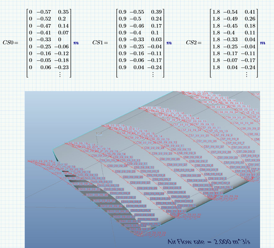
in the worksheet XFL and XFU are 2 arrays that are used to create the Lower and Upper surfaces.
The data needed to be reordered and trimmed down (if I remember right, there were duplicate points when the surfaces were combined.) and then stitched together to make one array (just because thats the way I wanted to export the data) The program below does that.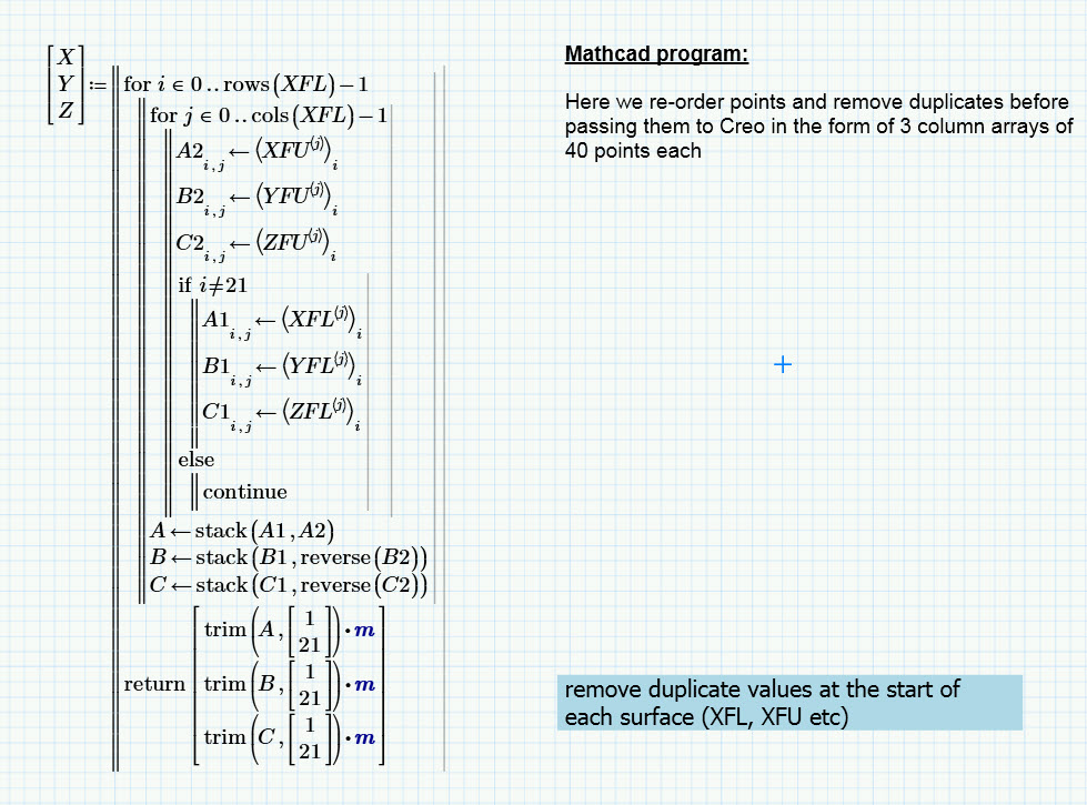
Now your XYZ data that you can either export in a file format of your choice using the variuos WRITE functions available
or
As I have done below use the Analysis feature based integration to connect Mathcad arrays to Creo.
The arrays, CS0, CS1 ...etc are created first
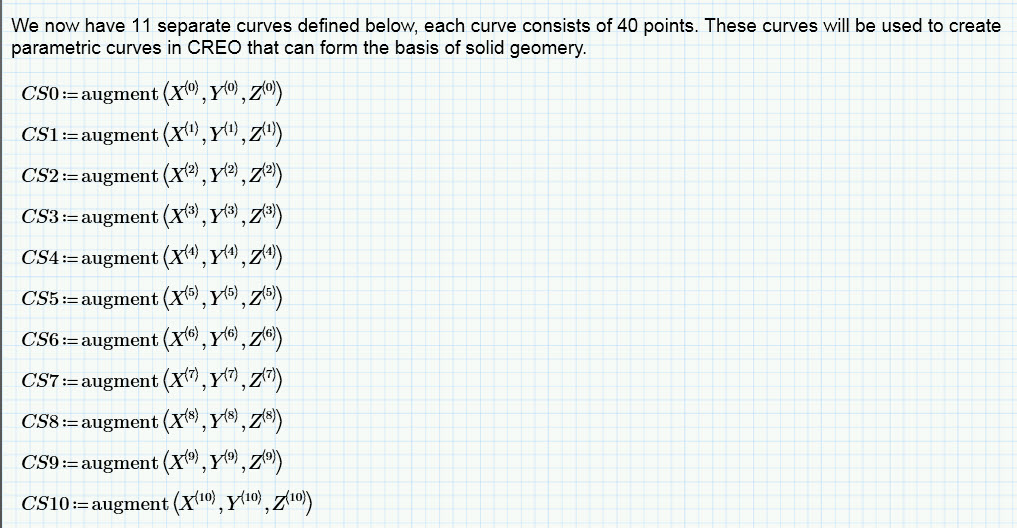
and then evaluated and assigned as inputs to Creo (from the Input/Output tab)
For other ways of data export from mathcad to CAD.
Have a read of this blog..http://blogs.ptc.com/2013/05/02/points-lines-and-triangles-oh-my/
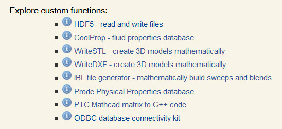
Here are some Mathcad functions( DLL's) to export data in certain formats.
WriteDXF and WriteSTL would be a start.
http://communities.ptc.com/docs/DOC-3621
(note you need to be on active support to download these)
My suggestion to you would be to try with something a little simpler first. perhaps a cylinder defined by a circular section. Create the section in Mathcad and connect the array that defines the section to Creo.
Perhapds explore which method works best for you.
Thomas
Jan 29, 2015
02:38 PM
- Mark as New
- Bookmark
- Subscribe
- Mute
- Subscribe to RSS Feed
- Permalink
- Notify Moderator
Jan 29, 2015
02:38 PM
Hi Thomas,
I just wanted to take this time to first say a big Thank you. I appreciate the very detailed answer. I just read thoroughly through your reply and from the details you have given, I now see a vision to achieving the results that I expect. I will spend the next couple of days working on the project. I will defintely write back to tell you how it all went.
Once again, thanks very much. It was a very helpful answer.
Jama
Dec 07, 2017
09:37 AM
- Mark as New
- Bookmark
- Subscribe
- Mute
- Subscribe to RSS Feed
- Permalink
- Notify Moderator

Jan 17, 2020
06:27 AM
- Mark as New
- Bookmark
- Subscribe
- Mute
- Subscribe to RSS Feed
- Permalink
- Notify Moderator
Jan 17, 2020
06:27 AM
Hello!
I receive an error message each time that I assignt the output values. Can you upload a similar worksheet? I don't understand how to assign the output values or what I am doing wrong.

Mar 28, 2020
12:38 AM
- Mark as New
- Bookmark
- Subscribe
- Mute
- Subscribe to RSS Feed
- Permalink
- Notify Moderator
Mar 28, 2020
12:38 AM
The equation of the line is y=−14x+1, and the curve looks like a sine curve y=sin(2πx4) (where x is scaled so that it makes a cycle from 0 to 4) added to that line. Therefore, y=−14x+1+Asin(2πx4) but the amplitude A is tricky from the figure, so perhaps choose A=0.15.
________________________________________________________________________________________