
Turn on suggestions
Auto-suggest helps you quickly narrow down your search results by suggesting possible matches as you type.
Showing results for
Turn on suggestions
Auto-suggest helps you quickly narrow down your search results by suggesting possible matches as you type.
Showing results for
Community Tip - You can subscribe to a forum, label or individual post and receive email notifications when someone posts a new topic or reply. Learn more! X
- Community
- Creo+ and Creo Parametric
- 3D Part & Assembly Design
- Re: How to place a tapped hole
Options
- Subscribe to RSS Feed
- Mark Topic as New
- Mark Topic as Read
- Float this Topic for Current User
- Bookmark
- Subscribe
- Mute
- Printer Friendly Page
How to place a tapped hole
Mar 28, 2016
12:00 PM
- Mark as New
- Bookmark
- Subscribe
- Mute
- Subscribe to RSS Feed
- Permalink
- Notify Moderator
Mar 28, 2016
12:00 PM
How to place a tapped hole
Greetings:
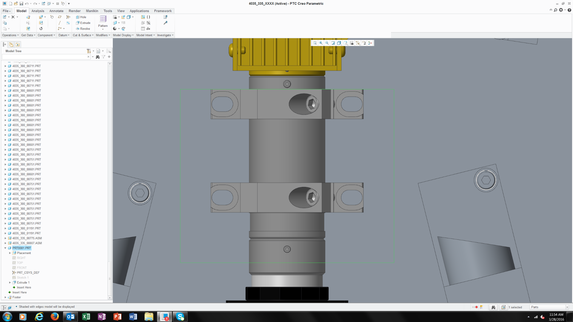
I am a new user been using Creo for 6 weeks, I come from the SW /Inventor/ Solid edge worlds. During my time using Creo I'm struggling to master some of the most basic modeling features that were relatively easy to create with the 3 CAD packages I mentioned. One issues that I can't seem figure out after 8 hours is how to place a tapped hole behind a thru slot on another part. I know how I would accomplish this on other programs but I just can't figure it out on Creo. below is a screen shot what I'm discussing. If anyone has a step by step approach it would be greatly appreciated, -Frank
This thread is inactive and closed by the PTC Community Management Team. If you would like to provide a reply and re-open this thread, please notify the moderator and reference the thread. You may also use "Start a topic" button to ask a new question. Please be sure to include what version of the PTC product you are using so another community member knowledgeable about your version may be able to assist.
Labels:
- Labels:
-
Data Exchange
6 REPLIES 6
Mar 28, 2016
06:20 PM
- Mark as New
- Bookmark
- Subscribe
- Mute
- Subscribe to RSS Feed
- Permalink
- Notify Moderator
Mar 28, 2016
06:20 PM
I imagine someone else out there might have an easier way, but I would create some simple construction geometry. My preference would be to create a axis in the clamp that represents the slot center, and then use this axis as the second reference for the hole feature. If you can't (or don't want to) modify the clamp, then you could also create similar construction geometry in the part getting the taps.

Mar 28, 2016
07:56 PM
- Mark as New
- Bookmark
- Subscribe
- Mute
- Subscribe to RSS Feed
- Permalink
- Notify Moderator
Mar 28, 2016
07:56 PM
This is very much a common practice on slots. In the sketcher there are 2 point types; geometry and construction. In the datum area of the menu, these are geometry and can be referenced after the sketch is closed (but visible) where construction geometry (points, axes and Csys) are only visible within the sketch. In extrudes, the geometry points extrude to datum axes.
Placing points is easier when you open the dialog tab. There are a lot of options hidden below there. However, Creo is weak on "midpoints" locations.
One thing... is it your practice to use assembly references in sub-models?
Mar 28, 2016
08:52 PM
- Mark as New
- Bookmark
- Subscribe
- Mute
- Subscribe to RSS Feed
- Permalink
- Notify Moderator
Mar 28, 2016
08:52 PM
Not sure if this was all directed at me or the OP, but yes, there are always 20 different ways to accomplish the same thing in Creo. To answer your assembly reference question, I imagine there are (at least) four different methodologies here:
- Create some extra geometry in the clamp (axis, point, curve, etc.) and then reference this from the tap. (Modification to the clamp model is required.)
- Create some extra geometry in the tapped model and then reference this by the tap. (Still have a reference back to the clamp model, but no modification of the clamp model is required.)
- Create some geometry in the parent assembly (or skeleton model) that defines the tap location.
- If this geometry is defined independently and then drives both the clamp and the tap locations, you basically have a "top down" design.
- If this geometry is instead driven by the clamp location, you basically have a "bottom up" design and the end result isn't much different from #1 and #2.
- Define the location of the tap manually with dimensions, completely unrelated to the clamp location (no references.)
Option 4 will provide actual dimensions that can be shown on a drawing for the tap location. Options 1 - 3 will not, since the tap location will be coaxially tied to the referenced axis.
I personally prefer option #1 since I can be confident that if the clamp moves position, the tap is going to move with it, and I don't need an abstract skeleton model to define the relationship. Granted, this requires manual creation of some drawing dimensions (for tap location), but I think the trade-off is worth it.
To take it even further, if you're willing create your own home-made hole features (UDFs), you can have the tap size automatically change when the clamp's screw size changes. Then both the tap location and tap size will correctly update when the parent (clamp slot) changes.
Mar 28, 2016
10:08 PM
- Mark as New
- Bookmark
- Subscribe
- Mute
- Subscribe to RSS Feed
- Permalink
- Notify Moderator
Mar 28, 2016
10:08 PM
The notes were to the OP.
Mar 28, 2016
10:24 PM
- Mark as New
- Bookmark
- Subscribe
- Mute
- Subscribe to RSS Feed
- Permalink
- Notify Moderator
Mar 28, 2016
10:24 PM
Never thought of bottom-up that way, Tom, meaning I am misusing the term. The closest I can come up with is "independent" where you don't rely on other models for the part files. Those references are easily lost during a design cycle. Most companies I've worked for will take the time to make sure each part model can stand on it's own. This was universal among 3 different parametric systems.
However, as a designer, I like the interactive relation driven features from a top level assembly development perspective. It is the ideal design layout. As a sole contributor (or close collaborator), this is a very powerful tool.
Also note that Frank is on a steep learning curve. Tech is probably a side note for now. But yes, knowing how Frank wants to interact with Creo will be useful.
Mar 29, 2016
02:13 AM
- Mark as New
- Bookmark
- Subscribe
- Mute
- Subscribe to RSS Feed
- Permalink
- Notify Moderator
Mar 29, 2016
02:13 AM
Top-down and bottom-up refers to how the design is controlled not whether or not the models are dependent on each other. It depends on what you are controlling and how.
