
Turn on suggestions
Auto-suggest helps you quickly narrow down your search results by suggesting possible matches as you type.
Showing results for
Turn on suggestions
Auto-suggest helps you quickly narrow down your search results by suggesting possible matches as you type.
Showing results for
Community Tip - New to the community? Learn how to post a question and get help from PTC and industry experts! X
- Community
- Creo+ and Creo Parametric
- 3D Part & Assembly Design
- Drawing Entity Colours
Options
- Subscribe to RSS Feed
- Mark Topic as New
- Mark Topic as Read
- Float this Topic for Current User
- Bookmark
- Subscribe
- Mute
- Printer Friendly Page
Drawing Entity Colours
Nov 17, 2010
08:02 AM
- Mark as New
- Bookmark
- Subscribe
- Mute
- Subscribe to RSS Feed
- Permalink
- Notify Moderator
Nov 17, 2010
08:02 AM
Drawing Entity Colours
Hi, I have recently been working with a company which use Inventor. They sent me across some drawings which were cosmetically superior (in my opinion of course) to mine. I would like to try and make mine a bit more like theirs. Below is a screen capture of what I'm talking about.
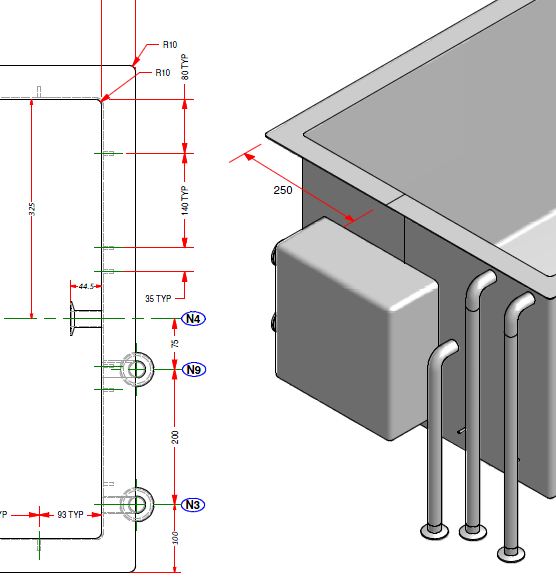
First up... how would I change my dimension leaders to red? I have tried editing my pen table file (pen 2 I believe?) but the colour doesn't change. Is there another way of achieving this?
Secondly, and I have requested this feature for years. I like the black lining around the shaded part, in drawing as well as in modelling mode. SolidWorks also does this. I think it makes it easier to see and visualise certain geometry.
Any feedback, comments or opinions?
Thanks
Lee
This thread is inactive and closed by the PTC Community Management Team. If you would like to provide a reply and re-open this thread, please notify the moderator and reference the thread. You may also use "Start a topic" button to ask a new question. Please be sure to include what version of the PTC product you are using so another community member knowledgeable about your version may be able to assist.
Labels:
- Labels:
-
2D Drawing
17 REPLIES 17
Nov 17, 2010
08:30 AM
- Mark as New
- Bookmark
- Subscribe
- Mute
- Subscribe to RSS Feed
- Permalink
- Notify Moderator
Nov 17, 2010
08:30 AM
Hi Lee,
Double clicking on the dimension (or right click -properties in tree browser) will pop up one dialog which will give you option to change the text/leader color.
I dont think ( as per my knowledge) there is option to set black lining around the shaded part for drawing and for modelling.
Regards,
Niraj
Nov 17, 2010
09:29 AM
- Mark as New
- Bookmark
- Subscribe
- Mute
- Subscribe to RSS Feed
- Permalink
- Notify Moderator
Nov 17, 2010
09:29 AM
Hi, thanks for the response.
Changing the colour in this way also changes the text to red, something I did not want to do. Also it is not very practical to do that every time I create a drawing. Can I assume there is an option in the config.pro for this? I would ideally like to change only the leader though and leave the text as it is. Anyone else have any suggestions?
Regarding the black outline, I think you are right, its not possible as I looked in to it a while ago.
Thanks,
Lee
Nov 18, 2010
04:03 AM
- Mark as New
- Bookmark
- Subscribe
- Mute
- Subscribe to RSS Feed
- Permalink
- Notify Moderator
Nov 18, 2010
04:03 AM
Lee,
To print yellow witness lines in red colour, you can use the following pen definition
pen 4 color 1.0 0.0 0.0; thickness 0.01 cm; letter_color
To display part with coloured edges, you can use the following procedure:
set config.pro option option ... show_shaded_edges yes
assign black colour to whole part
assign grey colour to all part surfaces
Martin
Martin Hanák
Nov 18, 2010
04:43 AM
- Mark as New
- Bookmark
- Subscribe
- Mute
- Subscribe to RSS Feed
- Permalink
- Notify Moderator
Nov 18, 2010
04:43 AM
Thats great.
Thank you Martin. I am also looking for same option.
Nov 18, 2010
05:24 AM
- Mark as New
- Bookmark
- Subscribe
- Mute
- Subscribe to RSS Feed
- Permalink
- Notify Moderator
Nov 18, 2010
05:24 AM
Hi Martin, many thanks for your reply and contribution to this thread.
pen 4 color 1.0 0.0 0.0; thickness 0.01 cm; letter_color
This line did not do anything to my witness lines in my drawings. I know for sure my pen table is being used as I tried the same line for pen 2 and it changed my witness lines red BUT also ALL text. Which is an undesired result. Do you have an idea why this isnt working?
Regarding the shaded view with black edges; I have seen this method suggested before, however I don't find it a viable long term solution. I will forget about this for now, but come on PTC this features has been requested often since I joined the forums back in 2006. Is it really that difficult to implement the feature? It can really help show, otherwise hidden, geometry.
Nov 18, 2010
06:00 AM
- Mark as New
- Bookmark
- Subscribe
- Mute
- Subscribe to RSS Feed
- Permalink
- Notify Moderator
Nov 18, 2010
06:00 AM
Lee,
You are right, pentable affects only print output.
To change colors on the screen, you have to use information provided by Burt Land
1.] In the existing drawing, set drawing option LINE_STYLE_STANDARD std_iso
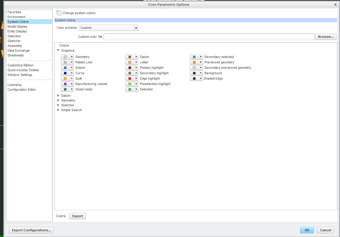
2.] Click View > Display Settings > System Colors
3.] Change following two colors to RED ... Letter, Highlight - Edge
Martin
Martin Hanák
Nov 18, 2010
05:20 AM
- Mark as New
- Bookmark
- Subscribe
- Mute
- Subscribe to RSS Feed
- Permalink
- Notify Moderator
Nov 18, 2010
05:20 AM
To have only red leaders on a screen drawing, in your Drawing Options file set
LINE_STYLE_STANDARD to std_iso
(this allows you to have different text and leader line styles)
Go to View>Display Settings>System Colors
Leader Color is controlled by Letter Color, so change it to RED
Text Color is controlled by High-Light Edge
Refresh the drawing.
The colors you get in the print are controlled by the *.pnt file - you will need to adjust them in that file if you want a colored print.
Heres a list of the various System Colors and the related drawing entity - whoever programmed this up was on planetPTC when they coded it - theres no rhyme or reason to any of it. Its taken hours to untangle the mess - hopefully its of some use to you. This had better not turn up in the new CREO.
!
! SYSTEM COLORS COLOR_NAME DRAWING ENTITY
! Geometry drawing_color outline geometry,section text/arrows
! Hidden Line half_tone_color hidden lines,datum axes/planes
! Sketch section_color sketch lines
! Curve datum curves
! Quilt quilt_color quilt edges
! Manuf Volume magenta_color quilt outlines
! Sheet Metal attention_color sheet metal
! Datum datum_color hidden lines,datum coords/axes/planes,datum tags
! Letter letter_color dim lines/leaders,gtol frames/leaders,
! hatching,threads,balloons & leaders,
! tables,surface finish,detail view boundaries,
! axes & centerlines
! Highlight-Primary highlite_color
! Highlight-Secondary dimmed_color tangent edges,section centerline,datum planes,coord x/y/z
! Highlight-Edge edge_highlite_color text in tables,balloons,details,notes,gtol,surface finishes
!
! Note
! LINE_STYLE_STANDARD affects text color as follows (it is set in the Drawing Options file)
! std_ansi - letter_color (detail view boundaries also altered)
! std_iso - edge_highlite_color
! std_jis - edge_highlite_color
! std_din - edge_highlite_color
Nov 18, 2010
05:36 AM
- Mark as New
- Bookmark
- Subscribe
- Mute
- Subscribe to RSS Feed
- Permalink
- Notify Moderator
Nov 18, 2010
05:36 AM
Hi thanks for the information. However, I do not find the LINE_STYLE_STANDARD option in the drawings option file. I added it manually but it doesn't appear to do anything. I changed Leter color to red, this changes leader lines and text to red. I changed High-light edge to black but nothing happens. The text stays red. I'm guess this is what the LINE_STYLE_STANDARD configuration option is for but it doesn't seem to work for me? (using WF5).
Nov 18, 2010
05:48 AM
- Mark as New
- Bookmark
- Subscribe
- Mute
- Subscribe to RSS Feed
- Permalink
- Notify Moderator
Nov 18, 2010
05:48 AM
LINE_STYLE_STANDARD doesnt appear because youre using your standard drawing options file and it doesnt contain it. When you open an old drawing you need to refresh it so the new Drawing Options file gets used - otherwise it just uses the imbedded old options. This works in WF4 and WF5.
To refresh go Update Current Sheet(s)
Nov 18, 2010
05:52 AM
- Mark as New
- Bookmark
- Subscribe
- Mute
- Subscribe to RSS Feed
- Permalink
- Notify Moderator
Nov 18, 2010
05:52 AM
Lee,
in Proe WF5 ... open a drawing and click File > Drawing options. Then go to the Miscellaneous options section at the bottom of the file. You must see line_style_standard option there.
Martin
Martin Hanák
Nov 18, 2010
06:18 AM
- Mark as New
- Bookmark
- Subscribe
- Mute
- Subscribe to RSS Feed
- Permalink
- Notify Moderator
Nov 18, 2010
06:18 AM
Ah! there it is! So how do I make this option standard so I dont have to manually change it everytime? Do I save this as my new .dtl file?
Nov 18, 2010
06:44 AM
- Mark as New
- Bookmark
- Subscribe
- Mute
- Subscribe to RSS Feed
- Permalink
- Notify Moderator
Nov 18, 2010
06:44 AM
Go to View>Display Settings>System Colors
Change the colors to what you want, then save the file.
In your config.pro point
SYSTEM_COLORS_FILE to the file - the startup directory isnt a bad place to store it.
Im not sure "Cosmetically Superior" cuts it when it comes to a drawing - its all about standards.
If your "Cosmetically Superior" drawing results in a supplier mistake you may have no legal redress.
I would be interested to see the outcome - could you please post some drawing fragments 
Nov 18, 2010
06:46 AM
- Mark as New
- Bookmark
- Subscribe
- Mute
- Subscribe to RSS Feed
- Permalink
- Notify Moderator
Nov 18, 2010
06:46 AM
Lee,
save the settings from current drawing into .dtl file (eg. drwconfig.dtl).
Then add the following option into config.pro, for example:
drawing_setup_file c:\YOUR_PATH\drwconfig.dtl
If you create new drawing, then ProE will copy drwconfig.dtl into new drawing.
In existing drawing, you have to click File > Drawing options and load drwconfig.dtl into it.
Martin
Martin Hanák
Nov 18, 2010
07:28 AM
- Mark as New
- Bookmark
- Subscribe
- Mute
- Subscribe to RSS Feed
- Permalink
- Notify Moderator
Nov 18, 2010
07:28 AM
I am getting closer to where I want to be with regards to the appearance of my drawings. By the way, I didn't know there were standards for drawings as far as colours were concerned
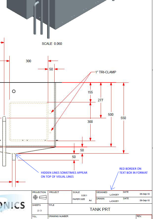
Below is a screen clipping of what I've got so far. It is an exported PDF. I have 2 issues.
1. Now that I have red dimension leaders, I also get a red border on text boxes. These text boxes are in my drawing format for automatic text such as date and "drawn by". Is it possible to change this without changing the leaders?
2. Hidden lines have always been kind of ugly and misleading for me. As you can see where I've pointed out on the screen clipping, sometimes the hidden line appears "on top" of the visual line. They are rather thick also, but I cant seem to get them any finer via the pen table.
I would love to see a clipping of everyone elses drawings to see how it compares . Any advice or tips on how I could further improve on this would be greatly appreciated.
Nov 18, 2010
08:27 AM
- Mark as New
- Bookmark
- Subscribe
- Mute
- Subscribe to RSS Feed
- Permalink
- Notify Moderator
Nov 18, 2010
08:27 AM
Lee,
Issue no.1
========
Red border has assigned "Letter" color. You changed "Letter" color from Yellow to Red. So border is red.
It is little bit difficult to tell you what you want to do.
E.g. you can return back "Letter" color to Yellow and modify manually the colour of all dimensions (RMB > Properties).
Issue no.2
========
To be able to drive PDF by pentable, you have to set config.pro options
pdf_use_pentable yes
use_8_plotter_pens yes
pen_table_file C:\PATH\pentable.pnt
and inside pentable use the following keywords for hidden lines:
pen 3 pattern 0.5, 0.2 cm; thickness 0.025 cm; color 0.0 0.0 0.0; half_tone_color
Martin
Martin Hanák
Nov 18, 2010
07:28 PM
- Mark as New
- Bookmark
- Subscribe
- Mute
- Subscribe to RSS Feed
- Permalink
- Notify Moderator
Nov 18, 2010
07:28 PM
Looking good - all your issues can be fixed with the pen table 
If you look at the list in my post up the top you will see all the color names - check your pen table to see how they are mapped to pens.
You might have to reassign some of them to different pens to correct the red pen being used on wrong items.
Dec 15, 2013
08:04 AM
- Mark as New
- Bookmark
- Subscribe
- Mute
- Subscribe to RSS Feed
- Permalink
- Notify Moderator
Dec 15, 2013
08:04 AM
@Lee Casey this might help you guys here u can change line colour edge colour etc
