
Turn on suggestions
Auto-suggest helps you quickly narrow down your search results by suggesting possible matches as you type.
Showing results for
Turn on suggestions
Auto-suggest helps you quickly narrow down your search results by suggesting possible matches as you type.
Showing results for
- Community
- Creo+ and Creo Parametric
- 3D Part & Assembly Design
- Hole problem/issue
Options
- Subscribe to RSS Feed
- Mark Topic as New
- Mark Topic as Read
- Float this Topic for Current User
- Bookmark
- Subscribe
- Mute
- Printer Friendly Page
Hole problem/issue
Oct 17, 2014
02:19 PM
- Mark as New
- Bookmark
- Subscribe
- Mute
- Subscribe to RSS Feed
- Permalink
- Notify Moderator
Oct 17, 2014
02:19 PM
Hole problem/issue
Hi,
Software PTC Creo 2.0
Hole “problem”. Are there any ways to create this using a sketch or any other tool to control the holes? As show in the drawing, holes are on different heights, but are all the same size.
I have tried a few things, but so far it have failed, or ended in regeneration error.
This thread is inactive and closed by the PTC Community Management Team. If you would like to provide a reply and re-open this thread, please notify the moderator and reference the thread. You may also use "Start a topic" button to ask a new question. Please be sure to include what version of the PTC product you are using so another community member knowledgeable about your version may be able to assist.
Labels:
- Labels:
-
2D Drawing
20 REPLIES 20
Oct 17, 2014
03:51 PM
- Mark as New
- Bookmark
- Subscribe
- Mute
- Subscribe to RSS Feed
- Permalink
- Notify Moderator
Oct 17, 2014
03:51 PM
Are you creating a point pattern of the same hole at the part level?
I created a sketch using lines so I could project them onto multiple surfaces. I created a single datum point feature with multiple points using the vertices of the projected sketch. I created an axis at the 1st instance hole so I could select the surface and axis for placement. I then used the point pattern. You need to understand this tip, however, select the origin! Use the point at the 1st instance to create the origin. I suggest you do this prior to selecting the point location feature because the black dots get in the way of selection.
The tip is something PTC really needs to look at. The 1st instance assumes a "feature center" as the starting point while placement according to the points is at the surface. This causes an offset of all the features including duplicating the 1st instance! The fact that you cannot select anything under the dots is a secondary issue that this interface really doesn't address. So setting the origin -before- selecting the point set is yet another Pro|WorkAround^tm to deal with this critical but little understood assumption by PTC. In this case, it is obvious, but there are all too many occasions when this offset is minute and perpetuates a significant error.
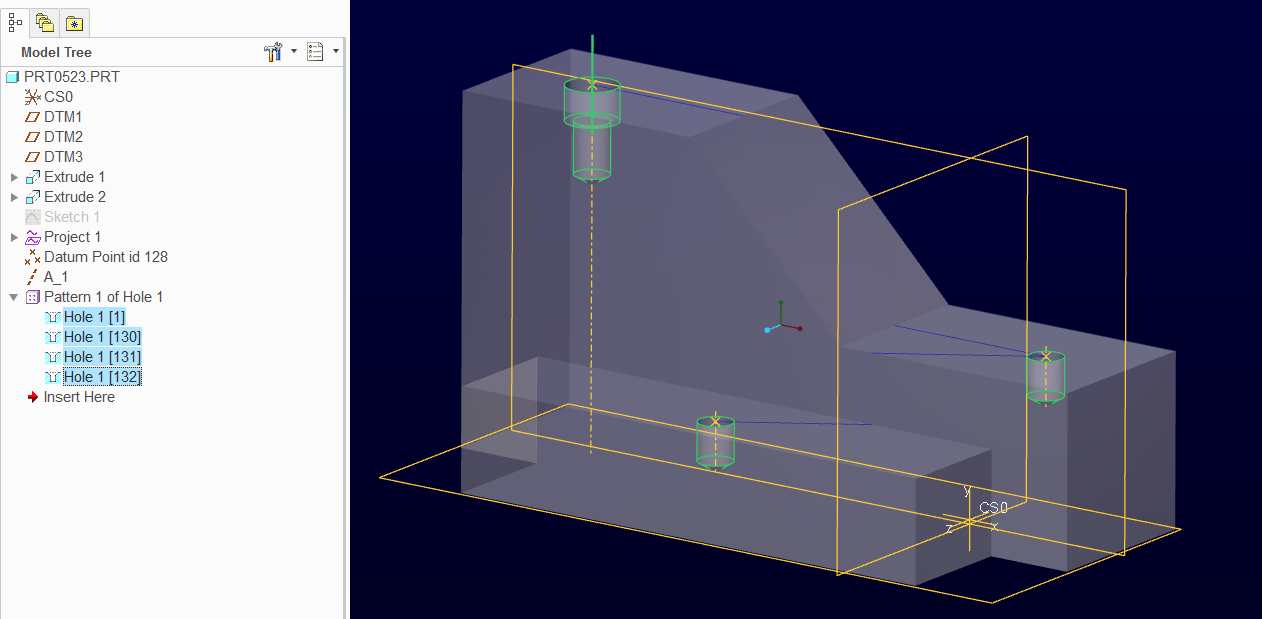
Correct pattern with selected origin:
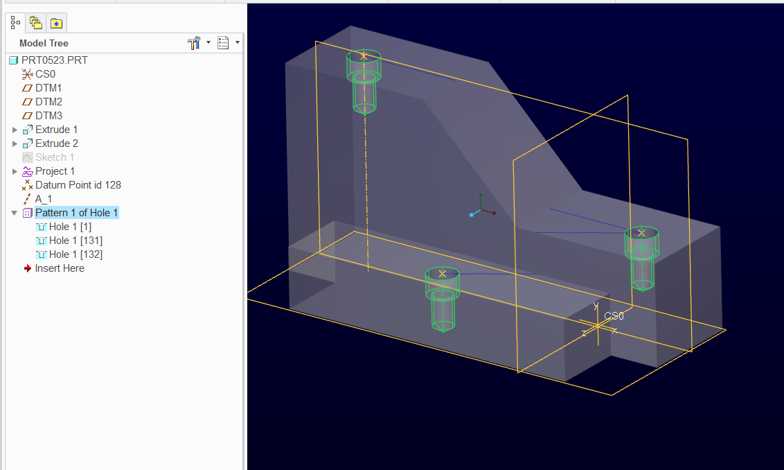
Default assumed origin
Oct 17, 2014
04:08 PM
- Mark as New
- Bookmark
- Subscribe
- Mute
- Subscribe to RSS Feed
- Permalink
- Notify Moderator
Oct 17, 2014
04:08 PM
This might highlight the issue with alternate origin selection. It is time I create a support case for this...
Oct 17, 2014
04:12 PM
- Mark as New
- Bookmark
- Subscribe
- Mute
- Subscribe to RSS Feed
- Permalink
- Notify Moderator
Oct 17, 2014
04:12 PM
Wow, great video, will try out this now
Oct 17, 2014
08:16 PM
- Mark as New
- Bookmark
- Subscribe
- Mute
- Subscribe to RSS Feed
- Permalink
- Notify Moderator
Oct 17, 2014
08:16 PM
I worked with customer support on this and they gave me two helpful options for selecting the point under the black dot.
1: turn on the tags for points. This makes the point selectable.
2: search for points and highlighting the search results will give you graphic feedback and selection capabilities.
Both of these work well while you are still in the pattern feature creation function. So this is good.
I did request that it still be reported to R&D because you cannot select a valid vertex under the black dot.
My take is that significant effort can be done in setting up a pattern and that not being able to select the origin is a problem if you have to backtrack to select it. Some pattern definitions are very involved and loosing that effort can be significant if not detrimental. My second issue was sustaining a design but in that case, you can pre-define an alternate origin feature and use the work-around listed as 1 or 2.
Oct 17, 2014
04:08 PM
- Mark as New
- Bookmark
- Subscribe
- Mute
- Subscribe to RSS Feed
- Permalink
- Notify Moderator
Oct 17, 2014
04:08 PM
Hi, and thanks for a quick reply 
I started a sketch at the top surface, then added point datums, added dimensions, do all datums are on the same level. I get this message:
This feature is defined with dimensions that are very small compared to the rest of the part.
You may want to change the part accuracy to be smaller than 7.72427e-05.
I have set the accuracy to Relative 0.0001, but it still failt.
I'm still new to Creo, but I will try your metheod now (just need to read it closely to understand it).
But thanks for the help so far.
Oct 17, 2014
04:22 PM
- Mark as New
- Bookmark
- Subscribe
- Mute
- Subscribe to RSS Feed
- Permalink
- Notify Moderator
Oct 17, 2014
04:22 PM
Antonius Dirriwachter wrote:
Are you creating a point pattern of the same hole at the part level?
It is on Assembly level
Oct 17, 2014
04:32 PM
- Mark as New
- Bookmark
- Subscribe
- Mute
- Subscribe to RSS Feed
- Permalink
- Notify Moderator
Oct 17, 2014
04:32 PM
In theory it will work the same in the assembly level.
Accuracy is a whole other can of worms. I suggest you look into absolute accuracy as well.
I have these in my config.pro:
enable_absolute_accuracy yes
default_abs_accuracy .00005
This will let you set your accuracy to absolute in part/asm properties and it will ignore part size to calculate accuracy. I suggest you learn more about this. There are other settings in config.pro that you may wish to learn more about.
If you save-as your model as a ZIP file from the save-as dialog, you can post it here by using the advanced editor (upper right of this UI). And let us know what you are using as hole parameters.
Oct 17, 2014
05:04 PM
- Mark as New
- Bookmark
- Subscribe
- Mute
- Subscribe to RSS Feed
- Permalink
- Notify Moderator
Oct 17, 2014
05:04 PM
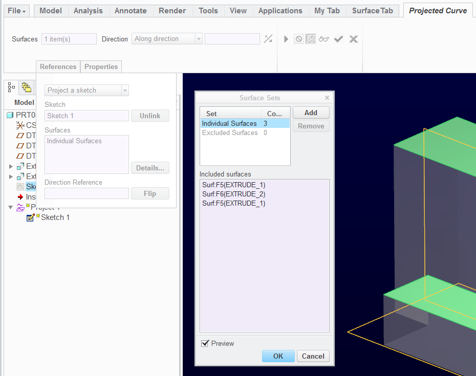
Under Project 1. Is it there you select the individual surfaces the points are to be projected to?
Oct 17, 2014
05:22 PM
- Mark as New
- Bookmark
- Subscribe
- Mute
- Subscribe to RSS Feed
- Permalink
- Notify Moderator
Oct 17, 2014
05:22 PM
I am projecting lines only onto the surfaces selected by the Project feature. I use the endpoints of the projected lines (vertices) to locate the points of the datum point set.
Oct 17, 2014
05:47 PM
- Mark as New
- Bookmark
- Subscribe
- Mute
- Subscribe to RSS Feed
- Permalink
- Notify Moderator
Oct 17, 2014
05:47 PM
Very sorry the the n00b questions, but I'm not able to select more than 1 surface under Project. Been searching the web a little for some info on the Project feature, but not much to find at all.
Oct 17, 2014
06:06 PM
- Mark as New
- Bookmark
- Subscribe
- Mute
- Subscribe to RSS Feed
- Permalink
- Notify Moderator
Oct 17, 2014
06:06 PM
Holding the Ctrl key is normally how you get multiple selections. You can also open the Details dialog to aid in selection.
Oct 17, 2014
06:10 PM
- Mark as New
- Bookmark
- Subscribe
- Mute
- Subscribe to RSS Feed
- Permalink
- Notify Moderator
Oct 17, 2014
06:10 PM
Thanks for you time
I tested this in a part, there I'm able to select multiple surfaces on at diffrent hights, but not in the assembly, so I
guess I need to make 1 project for each surface?
Oct 17, 2014
06:13 PM
- Mark as New
- Bookmark
- Subscribe
- Mute
- Subscribe to RSS Feed
- Permalink
- Notify Moderator
Oct 17, 2014
06:13 PM
Yep, I am just testing that. So you need one project for each object (part) in the assembly, however, all the points can be made as one point set. And the pattern will follow the point set into multiple components as a single pattern.
Oct 17, 2014
06:31 PM
- Mark as New
- Bookmark
- Subscribe
- Mute
- Subscribe to RSS Feed
- Permalink
- Notify Moderator
Oct 17, 2014
06:31 PM
Still failt here, not sure why. I can make single independent hole, but not when I chose axis and surface.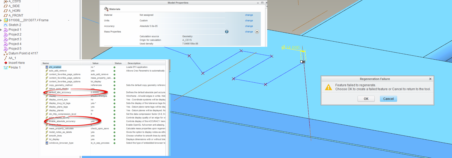
Oct 17, 2014
06:40 PM
- Mark as New
- Bookmark
- Subscribe
- Mute
- Subscribe to RSS Feed
- Permalink
- Notify Moderator
Oct 17, 2014
06:40 PM
I get it to work like a dream with extrude, still testing more on Hole.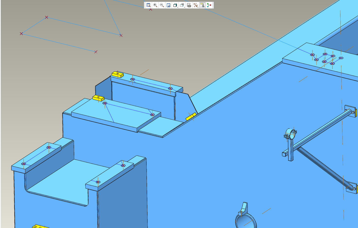
Oct 17, 2014
08:08 PM
- Mark as New
- Bookmark
- Subscribe
- Mute
- Subscribe to RSS Feed
- Permalink
- Notify Moderator
Oct 17, 2014
08:08 PM
Testing is the theme here indeed.
Is the axis a part feature or an assembly feature?
I made the axis an assembly feature and the hole transported well from one part to the next.
Oct 17, 2014
08:35 PM
- Mark as New
- Bookmark
- Subscribe
- Mute
- Subscribe to RSS Feed
- Permalink
- Notify Moderator
Oct 17, 2014
08:35 PM
I added the axis on the point, and used the surface as a reference. I will test axis as a assembly feature, as soon as I get to work tommorow 16 hours is enough for 1 day
But the weird thing is that it worked with extrude for me, but not hole. But I guess PTC Creo works in mysterious ways...sometimes...
I appreciate the help you have given me so far
Oct 17, 2014
08:42 PM
- Mark as New
- Bookmark
- Subscribe
- Mute
- Subscribe to RSS Feed
- Permalink
- Notify Moderator
Oct 17, 2014
08:42 PM
...PTC Creo works in mysterious ways...sometimes.
That is a great slogan. I might have to borrow that from time to time.
I will be away for much of tomorrow but we can pick this up later.
Oct 17, 2014
09:02 PM
- Mark as New
- Bookmark
- Subscribe
- Mute
- Subscribe to RSS Feed
- Permalink
- Notify Moderator
Oct 17, 2014
09:02 PM
Hehe...np
Sure we can pick it up later, I will test more tommorow
Oct 19, 2014
03:13 PM
- Mark as New
- Bookmark
- Subscribe
- Mute
- Subscribe to RSS Feed
- Permalink
- Notify Moderator
Oct 19, 2014
03:13 PM
I gave this option a try in assembly mode.
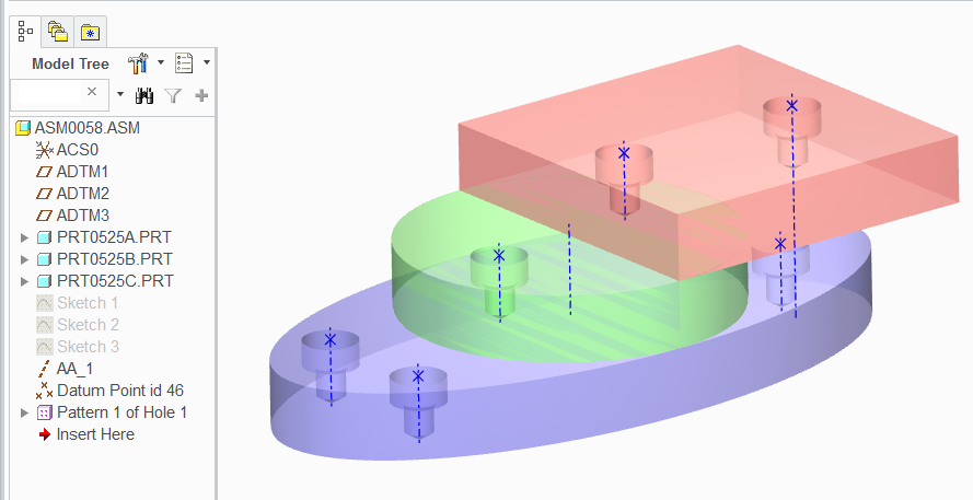
I created a sketch on each part at the assembly level using various references; both part and assembly. Sketch 1, 2 and 3 have geometry points fully defined.
Axis AA_1 was created from a point and surface reference.
And a common group of points was generated (datum point id 46) by picking all the sketched point. We don't have assembly datum intent features (only in part mode) so I had to recreate the set to put them in a single feature for point pattern selection.
Since each projection in our earlier conversation had to be a separate feature anyway, why not just create the sketch on the appropriate plane. Even if you have an over-reaching master sketch, you can use these references for the individual sketches for placing geometry points.
Please understand the difference in sketch mode between construction points and geometry point. Geometry points will create a datum point that remains selectable where a construction point does not once the sketch is closed. The Geometry point is created at the Datum tab where the construction point is in the Sketching tab. This is true of axes and coordinate systems as well.
Again, I had to pick the alternate origin in creating the pattern, but it is working very consistently when selecting the point feature in the assembly tree. Remember to show Features in the tree options.
Attached is the assembly in Creo 2.0 full version. Feel free to interrogate the model to see why this one is different from yours.
