
Turn on suggestions
Auto-suggest helps you quickly narrow down your search results by suggesting possible matches as you type.
Showing results for
Turn on suggestions
Auto-suggest helps you quickly narrow down your search results by suggesting possible matches as you type.
Showing results for
Community Tip - Learn all about the Community Ranking System, a fun gamification element of the PTC Community. X
- Community
- Creo+ and Creo Parametric
- 3D Part & Assembly Design
- Mirror of Part: Something's not right
Options
- Subscribe to RSS Feed
- Mark Topic as New
- Mark Topic as Read
- Float this Topic for Current User
- Bookmark
- Subscribe
- Mute
- Printer Friendly Page
Mirror of Part: Something's not right
Feb 14, 2015
07:05 AM
- Mark as New
- Bookmark
- Subscribe
- Mute
- Subscribe to RSS Feed
- Permalink
- Notify Moderator
Feb 14, 2015
07:05 AM
Mirror of Part: Something's not right
Mirroring in general is more complicated that it SHOULD be.
I have a part model that I need the opposite hand for. The most obvious way of creating this mirror model would be to go FILE/SAVE AS/MIRROR. The only problem is that you can NOT choose the plane to mirror from. WHY NOT? There is absolutely no reason this crucial step shouldn't be included.
There is a work around that involves extra un-needed steps.
This includes going into an Assembly and creating the mirror from this. Within Assembly it does allow you to specify the mirror plane.
I have followed PTC's specific directions to produce my needed mirrored part.
I specified the mirror plane from my original part (I also tried this with the Assembly mirror plane)
I am very happy with my result. See picture below (New mirror is in green)
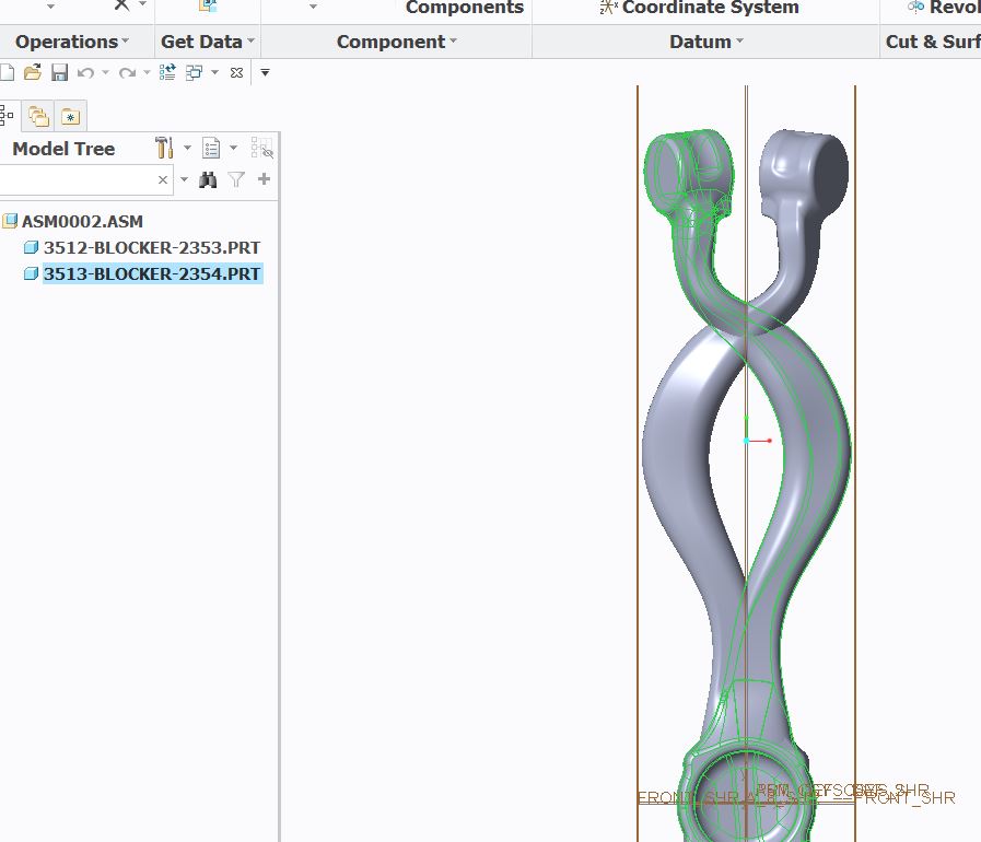
The satisfaction fades however as I see that my model is precisely the way it mirrored before. See picture below.
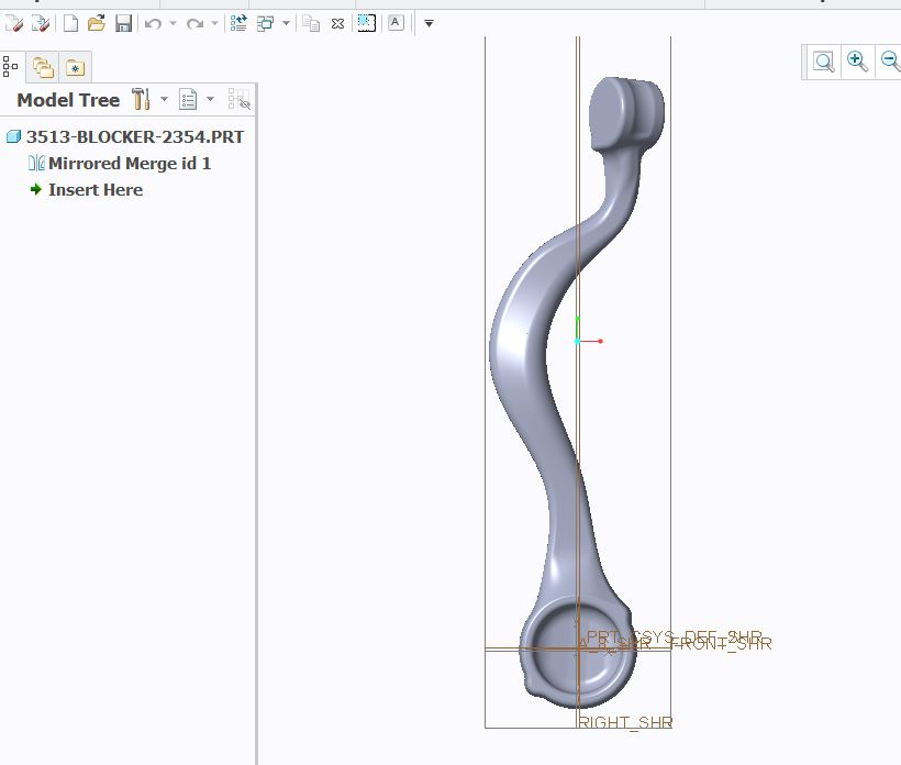
After the ensuing frustration I discovered that I could rotate my part so I was able to get the correct orientation. See picture below.
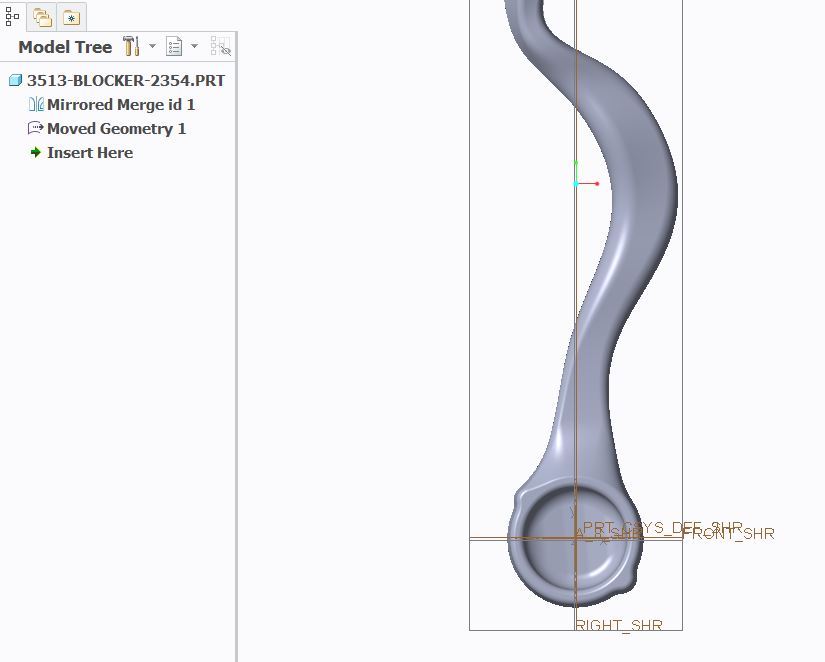
When I go back into Assembly after rotating the part I see that it displays incorrect to the view visibility within the part. See below picture
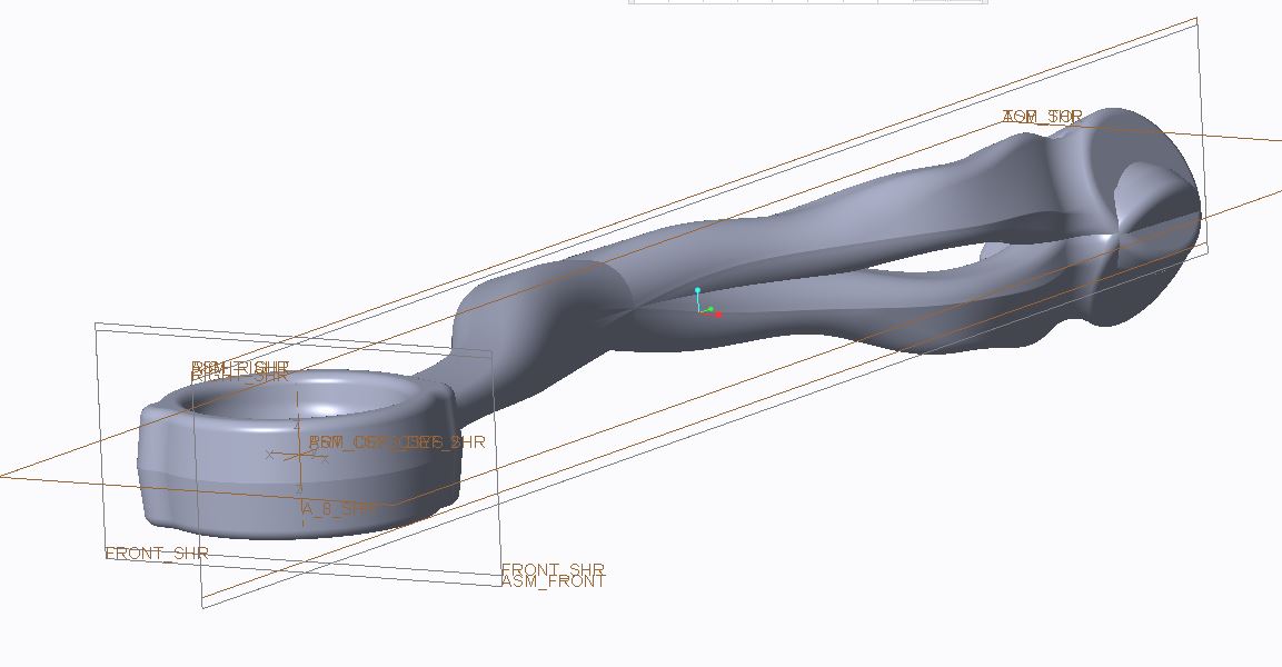
Any idea as to why my Part and Assembly models do not line up?
After this experience I voted up one of the Mirror part with specified plane Idea submissions.
What worries me however is that I have a mismatch between what I can view between Part and Assembly. This could lead to extremely expensive manufacturing results.
I did modify my planes to a World View Coordinate System. My views and Csys orientations appear to agree with each other in my Part and Assembly templates. This is the 1st such anomaly I've seen.
This thread is inactive and closed by the PTC Community Management Team. If you would like to provide a reply and re-open this thread, please notify the moderator and reference the thread. You may also use "Start a topic" button to ask a new question. Please be sure to include what version of the PTC product you are using so another community member knowledgeable about your version may be able to assist.
Labels:
- Labels:
-
2D Drawing
39 REPLIES 39
Feb 14, 2015
07:15 AM
- Mark as New
- Bookmark
- Subscribe
- Mute
- Subscribe to RSS Feed
- Permalink
- Notify Moderator
Feb 14, 2015
07:15 AM
just about the plane not included....a mirror would always be a mirror...which ever plane it is it would produce the same mirror part.
that is the reason a plane is not included.
Feb 14, 2015
07:35 AM
- Mark as New
- Bookmark
- Subscribe
- Mute
- Subscribe to RSS Feed
- Permalink
- Notify Moderator
Feb 14, 2015
07:35 AM
It does give you the actual part you need through a mirror but you have absolutely no control over where it gets mirrored to. I am not a very learned user of this software but I see 2 issues with this;
1) Due to componentizing sometimes you can't even select the part model as a whole to rotate into final position (I am running into this too)
2) If the model was built on a datum away from the origin you would have to go through another step to place it in it's needed position
In my situation I've spent over a half day struggling through a correct placement. Something which would take 10 seconds in our other CAD system.
This is one of the issues that I can foresee us starting a search for new CAD software. This HAS to work.
Feb 14, 2015
07:18 AM
- Mark as New
- Bookmark
- Subscribe
- Mute
- Subscribe to RSS Feed
- Permalink
- Notify Moderator
Feb 14, 2015
07:18 AM
it would be difficult to say something unless..actual part can be seen.
Feb 14, 2015
10:55 AM
- Mark as New
- Bookmark
- Subscribe
- Mute
- Subscribe to RSS Feed
- Permalink
- Notify Moderator
Feb 14, 2015
10:55 AM
I need to add to the original post and this situation is quite bad unless there is some setting that can fix this issue.
What I am finding is that everything that is mirrored whether the mirror part is created from using Save Part/Mirror or if it is mirrored from Assembly is that the resulting model file is rotated 180 degrees from where it really is.
In other words, the mirror did propagate in the correct orientation the issue is that the model file generated from the mirror is in the wrong orientation.
EDIT: Now I'm seeing that 1 model file mirrors over with the wrong model file orientation and the other model imports in the wrong orientation but a rotate lines it up in the proper model file orientation. This is severely buggy I literally don't know which ends up.
The way that I discovered this was by bringing the generated model file into Pro Mold and seeing that the model was rotated 180. I also noticed this issue by bringing another model into the generated mirror model file and seeing the orientation 180 degrees opposite of it's true orientation.
Even though I built my own Datums and Csys for my default part, assembly and Pro Mold they all line up with each other. This lines up with the spin center orientation. When I output data it is in true orientation with our other CAD system.
I don't understand how a mirror generated model file would rotate out of position. I'm hoping someone understands what needs done to straighten out the issue.
Feb 14, 2015
01:08 PM
- Mark as New
- Bookmark
- Subscribe
- Mute
- Subscribe to RSS Feed
- Permalink
- Notify Moderator
Feb 14, 2015
01:08 PM
The mirror operator flips the coordinate values relative to some plane. I don't know what plane part-mirror defaults to (probably X-Y, so plus-Z becomes negative-Z) but I guess the default isn't what you want. In the assembly you picked a different plane, and it mirrored like you wanted by using the same mirror as the part plus a rotation/offset to move the mirrored part to the desired location. If you go into that part and add more rotation, that rotation will be seen in the assembly.
I think I understand why you don't like the way it works, but there is no switch or command or any method that makes it work differently. I would probably create a new coordinate system in the mirrored part that was in the orientation and location I wanted.
Feb 14, 2015
11:44 PM
- Mark as New
- Bookmark
- Subscribe
- Mute
- Subscribe to RSS Feed
- Permalink
- Notify Moderator
Feb 14, 2015
11:44 PM
Looking even closer it appears that the models needing mirrored that had dual DCS ended up in a model file with DCS and views turned upside down to each other. In order to fix this I have to rebuild my views in order to insert properly into Pro Mold. This multiplied by every mirrored part.
This can't be. I've already drifted behind on this project I'm working on.
Feb 16, 2015
01:04 AM
- Mark as New
- Bookmark
- Subscribe
- Mute
- Subscribe to RSS Feed
- Permalink
- Notify Moderator
Feb 16, 2015
01:04 AM
Just out of curiosity, you said you went back to the ASM0002 assembly after modifying the 2513-BLOCKER-2354.PRT, and noticed that the mirror part is not oriented correctly. Did you also notice that this modified part is placed in the assembly using "Fix" constraint? If that's true, what happens if you change that "fix" constraint to "Default"?
By the way, how did you rotate the geometry of the 2513-BLOCKER-2354.PRT - that is, how did you create the "Moved Geometry 1" feature (I was trying to use flexible modeling, but it's not easy to precisely control the result!)
Feb 16, 2015
07:44 AM
- Mark as New
- Bookmark
- Subscribe
- Mute
- Subscribe to RSS Feed
- Permalink
- Notify Moderator
Feb 16, 2015
07:44 AM
Paul,
I did use the Default constraint when I placed the model in Assembly.
As far as the rotation of the part was concerned, this model was a quilt. That was actually why I was able to rotate the model.
The solid models that I mirrored I wasn't able to rotate unless I exploded the model and merged as a quilt.
Feb 16, 2015
01:03 PM
- Mark as New
- Bookmark
- Subscribe
- Mute
- Subscribe to RSS Feed
- Permalink
- Notify Moderator
Feb 16, 2015
01:03 PM
Hi Paul,
This is what I did and see if i understand what is happening to you. By the way, I wholeheartedly agree with you that the Creo mirror functionality has the serious limitation in that it always mirrors about the "internal" x-y plane.
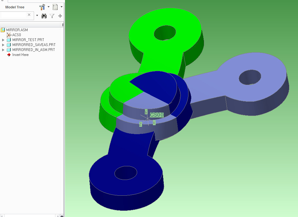
Shown in the image is an assembly of three components each constrained by "default".
Starting with the light blue part: if you do a save-as mirror function to that part you will end up with the dark blue part. Note that the mirror plane is the x-y plane of the default coordinate system.
Now, suppose what you actually want is the light green part - one that's been mirrored about they y-z plane. Well, if you use the assembly method of mirroring and create the mirror component (green - MIRRORED_IN_ASM) using the x-y plane of the light blue component, you will get what you see above, which looks great except as you mentioned, the green component is actually identical to the dark blue one. Creo merely does the same "x-y" mirror and then applied the "Fix constraint" to position the new part in the right location - in this assembly. In other words, if you change the "fix" constraint to "default", the green part will end up overlapping the dark-blue one.
So to get it to the right position, I transformed the geometry of the light green component by rotating it about its y-axis by 180 degrees. This modified component is now shown in the "default" orientation and is the correct mirror of the light-blue original. Also its views are preserved, etc...
I'm attaching my test files if you want to examine this. I know that this is a simple example and the corrective transformations can be much more complicated than a simple rotate about y-axis by 180 degrees, but that's how it is. The only other thing to keep in mind is to model your "to be mirrored" parts knowing that they will be flipped about the default x-y plane.
Feb 16, 2015
01:42 PM
- Mark as New
- Bookmark
- Subscribe
- Mute
- Subscribe to RSS Feed
- Permalink
- Notify Moderator
Feb 16, 2015
01:42 PM
Paul,
This appears to be the same type of issue I am seeing. In the end you have to rotate the part 180 degrees in order to be in the exact position it will need to be in the die.
Unfortunately I can't model the part to correspond with the way Creo mirrors the part as my original model file would need to be in it's needed position for the die. (Opposite hand part)
I need the interim model file to be in correct position to where it ends up in the die. What I have found as a work around at this point is to merge in the original model into the opposite hand model file. I will explode the solid, mirror it into position within the new model and re-solidify the model file. This give me the model in exact position that will be inserted into the die.
I would prefer the mirror operation to be a simple operation where you can choose the mirror plane and it will not mess up the CSYS orientation. I can easily do this in our other CAD software.
Feb 16, 2015
02:06 PM
- Mark as New
- Bookmark
- Subscribe
- Mute
- Subscribe to RSS Feed
- Permalink
- Notify Moderator
Feb 16, 2015
02:06 PM
Why can't you create a new CSYS that aligns the part the way you want?
Feb 16, 2015
02:15 PM
- Mark as New
- Bookmark
- Subscribe
- Mute
- Subscribe to RSS Feed
- Permalink
- Notify Moderator
Feb 16, 2015
02:15 PM
David,
That would be nice but you can't place a feature in front of the mirrored merge.
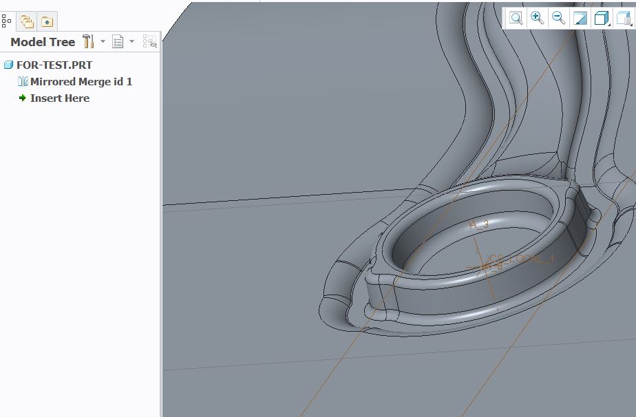
You can't place a feature above mirrored merge id 1.
Feb 16, 2015
02:50 PM
- Mark as New
- Bookmark
- Subscribe
- Mute
- Subscribe to RSS Feed
- Permalink
- Notify Moderator
Feb 16, 2015
02:50 PM
You don't have to.Create a new CSYS, oriented and located where you want, and use that instead of Default or Fixed as the assembly constraint.
Feb 16, 2015
03:57 PM
- Mark as New
- Bookmark
- Subscribe
- Mute
- Subscribe to RSS Feed
- Permalink
- Notify Moderator
Feb 16, 2015
03:57 PM
I didn't know you could place parts in assembly by CSYS.
I don't see the option available for this, what constraint type and component reference type would you use to select in this manner?
Feb 16, 2015
04:13 PM
- Mark as New
- Bookmark
- Subscribe
- Mute
- Subscribe to RSS Feed
- Permalink
- Notify Moderator
Feb 16, 2015
04:13 PM
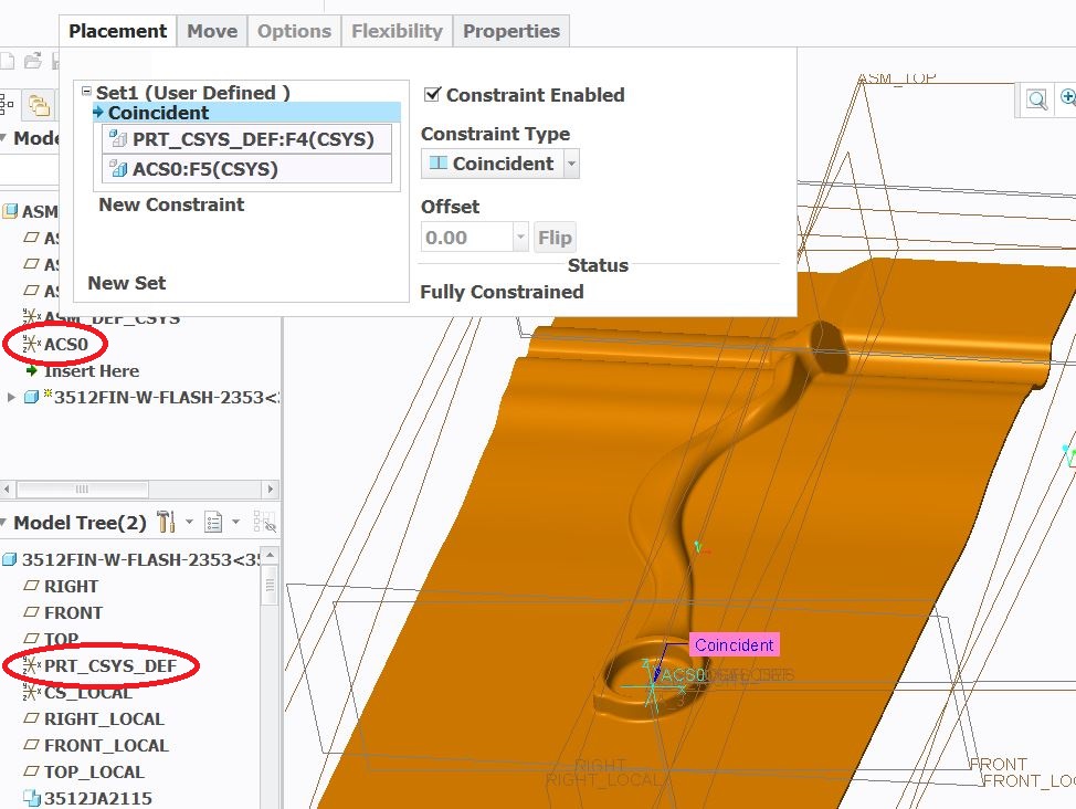
You can use "coincident" constraint and for references use the transformed csys in the part and the ACS0 (default one) in the assembly.
That would be much easier than moving around surfaces in the mirrored part and resolidifying them.
I thought you had the specific requirement of maintaining the "correct" orientation relative to the default coordinate system.
Feb 16, 2015
04:46 PM
- Mark as New
- Bookmark
- Subscribe
- Mute
- Subscribe to RSS Feed
- Permalink
- Notify Moderator
Feb 16, 2015
04:46 PM
It appears I'm getting the same results by choosing CSYS in part and assembly. The end result has the new part's Z direction in CSYS pointing in the down direction and not in the up direction as the original.

Feb 16, 2015
07:28 PM
- Mark as New
- Bookmark
- Subscribe
- Mute
- Subscribe to RSS Feed
- Permalink
- Notify Moderator
Feb 16, 2015
07:28 PM
That's why you create a -new- Csys.
Feb 17, 2015
07:03 AM
- Mark as New
- Bookmark
- Subscribe
- Mute
- Subscribe to RSS Feed
- Permalink
- Notify Moderator
Feb 17, 2015
07:03 AM
I did point to the new CSYS I built in Assembly. That would be the ASC0.
Feb 17, 2015
08:00 AM
- Mark as New
- Bookmark
- Subscribe
- Mute
- Subscribe to RSS Feed
- Permalink
- Notify Moderator
Feb 17, 2015
08:00 AM
David,
I went a little further into your method of mirroring in assembly. We use an extra CSYS for our parts because you can't rotate a solid.
I set up this experiment with this time removing the extra set of CSYS knowing I wouldn't rotate the part in true position, but at least I could see whether the extra set of CSYS factored into the problem. Using this setup I tried your method. I was very pleased to see that it actually worked!
That was fine but there still was an issue with the fact that I needed to use a double set of CSYS and I've already seen this as a failure using the method you suggested.
Then I asked myself which CSYS did I use from the parent model file? This time around I selected the default CSYS from the parent model when lining it up with the ASC0. To my amazement this worked perfectly.
Perhaps there are other dynamics involved that I've not uncovered but for the time being it appears that you've solved the "Mirroring: Something's not right" issue.
Thanks so much!!!
Feb 16, 2015
08:07 AM
- Mark as New
- Bookmark
- Subscribe
- Mute
- Subscribe to RSS Feed
- Permalink
- Notify Moderator
Feb 16, 2015
08:07 AM
Have you tried visual mirror or mirroring the part with the simple mirror tool just double Check.there you have the option to select the plane also
Feb 16, 2015
08:25 AM
- Mark as New
- Bookmark
- Subscribe
- Mute
- Subscribe to RSS Feed
- Permalink
- Notify Moderator
Feb 16, 2015
08:25 AM
Visual Mirroring would not work as we have to build actual tooling geometry on that which was mirrored and cutter paths have to be applied to this.
Feb 16, 2015
11:00 AM
- Mark as New
- Bookmark
- Subscribe
- Mute
- Subscribe to RSS Feed
- Permalink
- Notify Moderator
Feb 16, 2015
11:00 AM
yes i know..it would not create an actual part..i suggested you that for the following reasons:
1. you have an option to select a plane, which you do not have in "save a copy as mirror "..option.
2. you would be able to see whether that is giving you the same or different result.
you could also use the regular mirror option...where you can select the plane option and mirror ..and then cut the original geometry.
you can also use the merge inheritance option to call the original part in a new part window..then mirror it..and cut the original geometry.
Feb 16, 2015
03:40 PM
- Mark as New
- Bookmark
- Subscribe
- Mute
- Subscribe to RSS Feed
- Permalink
- Notify Moderator
Feb 16, 2015
03:40 PM
Rohit:
you can also use the merge inheritance option to call the original part in a new part window..then mirror it..and cut the original geometry.
Yes, so far that seems to be the best method I've stumbled into so far.
Feb 19, 2015
08:29 AM
- Mark as New
- Bookmark
- Subscribe
- Mute
- Subscribe to RSS Feed
- Permalink
- Notify Moderator
Feb 19, 2015
08:29 AM
I hate to say this but I can't seem to duplicate that which I thought was an answer. I do appreciate the help you've already given. Hopefully there is a simple reason for the failure that still persists.
I don't know if there was something different and unique in my trial model or if it was my perception of the results.
I will attach snapshots of what I am seeing. In what I've seen the whole crux of the issue is that the mirror function doesn't know how to deal with the CSYS Local that we use to rotate the solid part.
1st of all I placed the ASCO CSYS in the assembly. The placement of this didn't seem to influence the result. Whether the ASCO was rotated 180 or placed straight up the result I received was the same.
I inserted the component that I needed mirrored using the Coincident constraint. For the component I used the PRT_CSYS_DEF. For the Assembly I used the ASCO which I created.
Next I set up the Mirror operation. This was done using the Create Component command. I used the mirror part option. I part referenced the inserted component. I planar referenced the RIGHT datum which I needed the mirror completed off of.
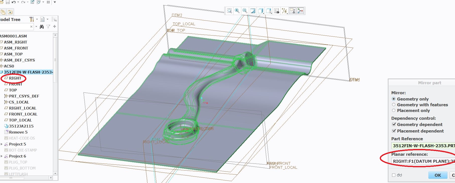
This mirrored the part. On 1st inspection the mirror looks correct. Unfortunately when you zoom into the CSYS area you see that the new part has a flipped Z orientation as shown.
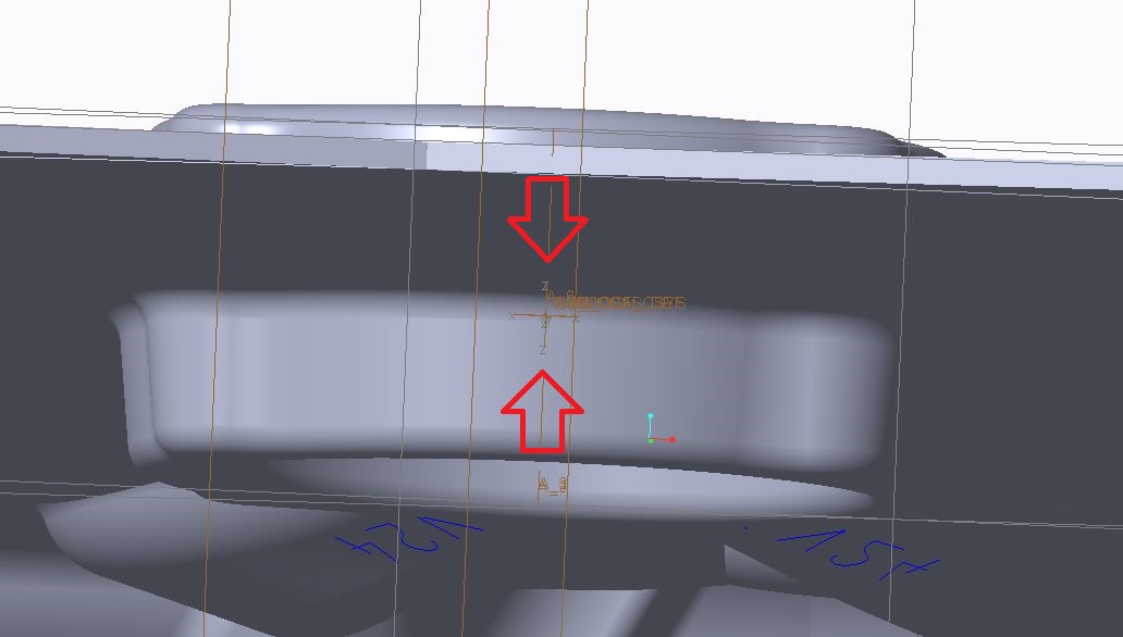
This unfortunately means that the part that you Open has the views flipped. When you bring this part into another model such as Pro Mold you see that it is rotated 180 degrees out of position.
I'm trying to get help additionally from PTC tech support, but there are times when people who have to deal with the tools within Creo have a deeper understanding of how the software works.
Feb 19, 2015
10:25 AM
- Mark as New
- Bookmark
- Subscribe
- Mute
- Subscribe to RSS Feed
- Permalink
- Notify Moderator
Feb 19, 2015
10:25 AM
Hi Paul,
Check again how the mirrored component is placed in the assembly. I'm suspecting it is using the "Fix" constraint.
Go edit the mirrored part and add to it a new CSYS, using the default PRT_CSYS_DEF as the reference.
This new CSYS will be transformed by rotating about some axis of PRT_CSYS_DEF by 180 degrees (I'm not sure which, try Y-axis).
Then go back to the assembly and redefine the placement of the mirrored part: use the coincident constraint between ACS0 and the new CSYS you just made.
This will position your mirrored part correctly in the assembly. In the same manner, you have to bring in the mirrored part into Pro Mold using the transformed CSYS...
And yes, unfortunately the views in your mirrored part will be flipped around.
The alternative is to move the mirrored geometry around to locate it correctly relative to the part's default csys.
That seems harder than redefining the orientation of some drawing views...
Feb 19, 2015
12:23 PM
- Mark as New
- Bookmark
- Subscribe
- Mute
- Subscribe to RSS Feed
- Permalink
- Notify Moderator
Feb 19, 2015
12:23 PM
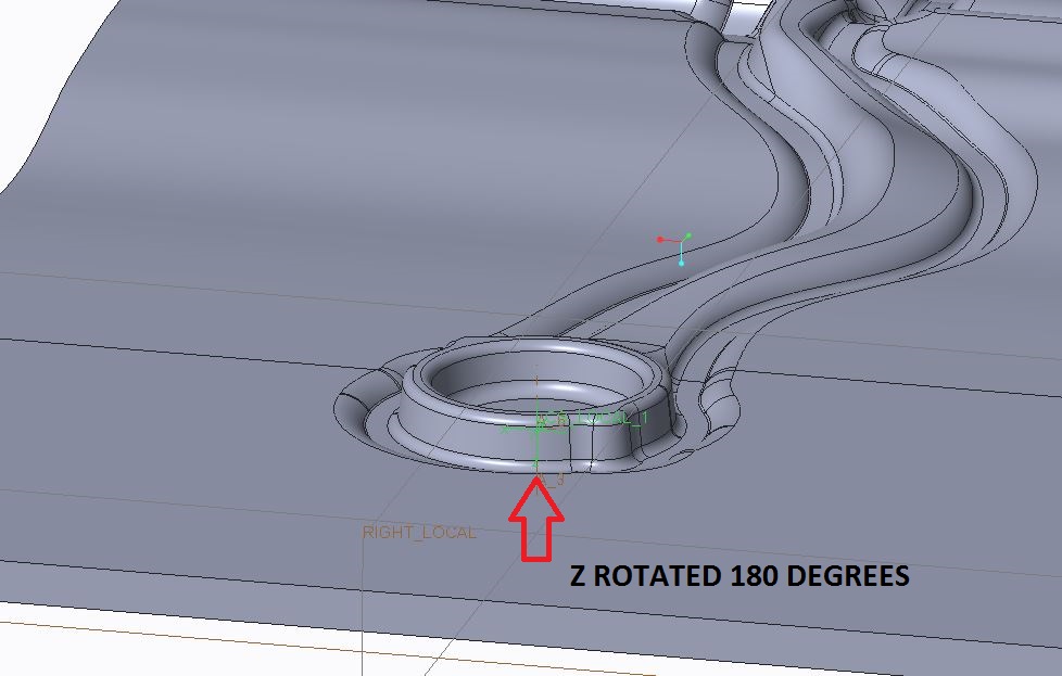
I've attached a simple part that uses our start part.
I think if anyone were to try the mirror sequence they would find the CSYS mirrors in upside down position and rotated 180 degrees away from the desired orientation.
Feb 19, 2015
01:20 PM
- Mark as New
- Bookmark
- Subscribe
- Mute
- Subscribe to RSS Feed
- Permalink
- Notify Moderator
Feb 19, 2015
01:20 PM
Sorry Paul, I can't open your file. You are using Creo 3.0? - I'm on 2.0...
Anyway, I think we are going in circles; I don't dispute that your mirrored part comes out in "wrong position" relative to its default CSYS. It is a direct consequence of you trying to mirror about Y-Z plane and Creo will only mirror about the X-Y plane.
Feb 19, 2015
01:32 PM
- Mark as New
- Bookmark
- Subscribe
- Mute
- Subscribe to RSS Feed
- Permalink
- Notify Moderator
Feb 19, 2015
01:32 PM
Paul,
Sorry you can't open this.
I do have a tendency to agree with you that the results show a mirror in only one plane direction even though you select the plane it needs to mirror about.
Creo appears to cheat by giving a visual impression that the needed mirror was accomplished.
This really sucks. Not only do you have to fix the rotation you also have to fix the views that it places to perform the visual cheat.
Having another much more inexpensive CAD software that applies a correct mirror in about 10 seconds really makes you hate Creo's ineptness.
Feb 19, 2015
05:07 PM
- Mark as New
- Bookmark
- Subscribe
- Mute
- Subscribe to RSS Feed
- Permalink
- Notify Moderator
Feb 19, 2015
05:07 PM
Many places use a Mapkey to redefine the views so it's a 10 second process. Views are typically defined parametrically; if they are defined relative to the datum planes, the datum planes will appear in the same orientations as before; the solid geometry will appear to move, so that what appeared to be the top view of the part will result in a bottom view of the mirror - which is exactly what mirrors do.
The alternative to reversing the sign of the Z coordinate to create a mirror part is to use floating point transformations which can result in features failing to regenerate in the mirror that successfully worked in the original part; even if they don't fail they can be distorted by round-off or truncation errors.
I'm still missing what 'upside down and rotated 180 degrees' means to you. In this picture you say Z is rotated 180 degrees, but Z is an axis and cannot rotate. If it was mirrored, then the part would have a left-hand coordinate system, which AFAIK PTC doesn't support. It looks like the part is rotated 180 degrees about Y in the image, but the colors chosen blend too much to make out whatever detail you are emphasizing. Rotate the view around Y and the Z axis will point up.
It would help if the comparison images were from similar points of view, and similar scales and not have overlapping parts. I really can't tell what the difference is from zooming in on a CSYS that is the same size no matter how zoomed up it is. The above image cropped off the main feature that I use to tell if it is the mirror part and what the orientation is.
It would also help if you included a picture of the feature definition for all the new coordinate systems you made to show what the transformation definition was. When you show you are using a new one, it doesn't show that it was defined correctly. By default a new CSYS will have the exact same orientation and location as the default or previously selected CSYS. I suspect that's why it appeared to work one time and not another; it actually worked the same, but the definitions were different so the results looked different.
