
Turn on suggestions
Auto-suggest helps you quickly narrow down your search results by suggesting possible matches as you type.
Showing results for
Turn on suggestions
Auto-suggest helps you quickly narrow down your search results by suggesting possible matches as you type.
Showing results for
Community Tip - New to the community? Learn how to post a question and get help from PTC and industry experts! X
- Community
- Creo+ and Creo Parametric
- 3D Part & Assembly Design
- Pattern along a curve but change orientation accor...
Options
- Subscribe to RSS Feed
- Mark Topic as New
- Mark Topic as Read
- Float this Topic for Current User
- Bookmark
- Subscribe
- Mute
- Printer Friendly Page
Pattern along a curve but change orientation according to different curve
Mar 06, 2024
08:47 PM
- Mark as New
- Bookmark
- Subscribe
- Mute
- Subscribe to RSS Feed
- Permalink
- Notify Moderator
Mar 06, 2024
08:47 PM
Pattern along a curve but change orientation according to different curve
Creo Parametric 8.0.7.0
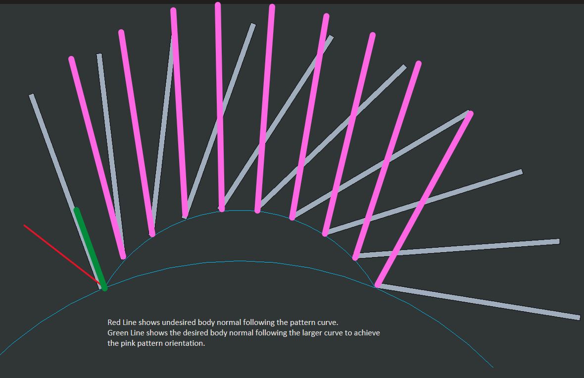
I am trying to achieve a curve pattern that follows a specific curve, but changes its orientation according to another curve. I thought the "Follow Shape Surface" might be able to help with this, but I have never been successful in generating a pattern with that option turned on.
Hopefully the pictures included give a clear idea of what I am trying to achieve. I can share models and methods I've tried if required, but it might only mislead the discussion at this time.
Solved! Go to Solution.
Labels:
- Labels:
-
General
1 ACCEPTED SOLUTION
Accepted Solutions
Mar 07, 2024
01:46 AM
- Mark as New
- Bookmark
- Subscribe
- Mute
- Subscribe to RSS Feed
- Permalink
- Notify Moderator
Mar 07, 2024
01:46 AM
One way I can think of doing this in part mode is as follows:

point PNT0 is defined to be "on curve", some distance or % away from one of its ends.
Extrude 1 section is made to use PNT0 as the anchor point and the larger radius curve as the reference. The central construction line is perpendicular to this reference.
Thus the Extrude 1 "arrow tip" will be always be pointing in the normal direction to the large curve.
(note PNT0 is "absorbed" by dragging it into Extrude1)
Now use dimension pattern to multiply extrude 1, varying the distance of its internal anchor point:

End result:

Note the reference curve can be a more complicated composite curve.

But seems it cannot be a spline.
4 REPLIES 4
Mar 07, 2024
01:46 AM
- Mark as New
- Bookmark
- Subscribe
- Mute
- Subscribe to RSS Feed
- Permalink
- Notify Moderator
Mar 07, 2024
01:46 AM
One way I can think of doing this in part mode is as follows:
point PNT0 is defined to be "on curve", some distance or % away from one of its ends.
Extrude 1 section is made to use PNT0 as the anchor point and the larger radius curve as the reference. The central construction line is perpendicular to this reference.
Thus the Extrude 1 "arrow tip" will be always be pointing in the normal direction to the large curve.
(note PNT0 is "absorbed" by dragging it into Extrude1)
Now use dimension pattern to multiply extrude 1, varying the distance of its internal anchor point:
End result:
Note the reference curve can be a more complicated composite curve.
But seems it cannot be a spline.
Mar 07, 2024
03:25 AM
- Mark as New
- Bookmark
- Subscribe
- Mute
- Subscribe to RSS Feed
- Permalink
- Notify Moderator
Mar 07, 2024
03:25 AM

Mar 07, 2024
12:54 PM
- Mark as New
- Bookmark
- Subscribe
- Mute
- Subscribe to RSS Feed
- Permalink
- Notify Moderator
Mar 07, 2024
12:54 PM
Thanks for the response! Unfortunately, I am unable to open your file since it's a newer version. Is your method similar to pausob response above by using the dimension pattern? Or were you able to achieve this with a curve pattern?
Mar 07, 2024
08:54 PM
- Mark as New
- Bookmark
- Subscribe
- Mute
- Subscribe to RSS Feed
- Permalink
- Notify Moderator
Mar 07, 2024
08:54 PM
This is a method to use a spline to drive a pattern including a reference to be normal to the spline for each pattern instance. This may be useful for what you are attempting to achieve. Creo 7 model enclosed for reference.

========================================
Involute Development, LLC
Consulting Engineers
Specialists in Creo Parametric
Involute Development, LLC
Consulting Engineers
Specialists in Creo Parametric
