
Turn on suggestions
Auto-suggest helps you quickly narrow down your search results by suggesting possible matches as you type.
Showing results for
Turn on suggestions
Auto-suggest helps you quickly narrow down your search results by suggesting possible matches as you type.
Showing results for
Community Tip - Did you get an answer that solved your problem? Please mark it as an Accepted Solution so others with the same problem can find the answer easily. X
- Community
- Creo+ and Creo Parametric
- 3D Part & Assembly Design
- RE: Family Table Copy Geometry Interaction
Options
- Subscribe to RSS Feed
- Mark Topic as New
- Mark Topic as Read
- Float this Topic for Current User
- Bookmark
- Subscribe
- Mute
- Printer Friendly Page
RE: Family Table Copy Geometry Interaction
Sep 07, 2023
04:42 PM
- Mark as New
- Bookmark
- Subscribe
- Mute
- Subscribe to RSS Feed
- Permalink
- Notify Moderator
Sep 07, 2023
04:42 PM
RE: Family Table Copy Geometry Interaction
Hello all,
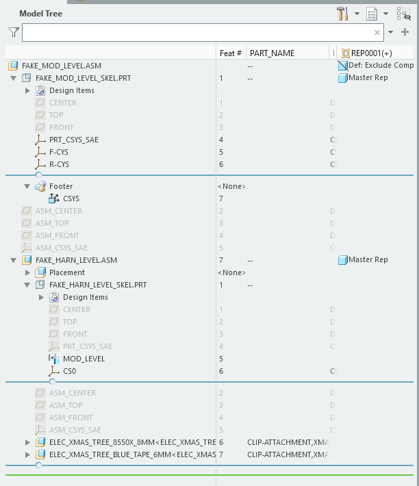
I am trying to create an upper level skeleton file that its parent assembly can leverage the "substitute" feature in the view manager to cascade changes to lower parts.
Below this "Module" level assembly would be a sub assembly that contains its own skeleton file aka "Sub Skeleton* that is leveraged for a flexible part. In this sub skeleton I am trying to use copy geometry to look "Up" at the family table as a whole.
The interaction I am looking for is as such. The Module level skeleton will have a Csys that will adjust between two determined "X" coordinate locations.
The Sub-Assembly I want to look at the family table and simply look at the location depending on what instance is leveraged, but my intention is that this sub-assembly will not have to be two separate parts because it is trying to view get ID's from what thinks is two separate feature ID's.
Does anyone have any idea of this is possible, or have a suggested way of doing this?
Labels:
- Labels:
-
Flexible Modeling
-
General
2 REPLIES 2
Sep 07, 2023
06:23 PM
- Mark as New
- Bookmark
- Subscribe
- Mute
- Subscribe to RSS Feed
- Permalink
- Notify Moderator
Sep 07, 2023
06:23 PM
Your written description indicates to me that you are creating a circular reference. The sub assembly is looking to a parent assembly FT instance to modify the placement of a csys in the sub assembly. It might be possible, but I am not clear on the parent child chain when using the substitute function in the view manager.
If I am not interpreting this accurately, more information is needed.
What version of Creo? Draw an intent map showing the parent child relationships and how design intent would be propagated between the models. Describe how you would like the design intent to behave at a high level and then you will get some options.
========================================
Involute Development, LLC
Consulting Engineers
Specialists in Creo Parametric
Involute Development, LLC
Consulting Engineers
Specialists in Creo Parametric
Sep 08, 2023
11:44 AM
- Mark as New
- Bookmark
- Subscribe
- Mute
- Subscribe to RSS Feed
- Permalink
- Notify Moderator
Sep 08, 2023
11:44 AM
There should not be a circular reference as far as I can see. Its just propagating design intent from the top down. Please reference the attached files. I am also using Creo 8.
When an operator opens up my master model, they select the designated names representation.
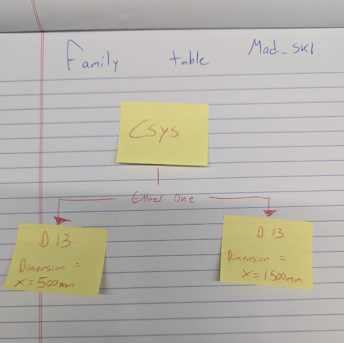
When they do this, I would like to have a family table activated that changes the location of a flexible part down the tree. Being it is a flexible part and not a fixed part, the part itself does not change and do to how the BOM is managed I don't wish to have the flexible part be forced to be two separate models. My intention is to have everything in the sub part related to a CSYS in an upper level skeleton file. That upper level skeleton file then would have a family table that shifts the CSYS in a direction by a prescribed distance. This should theoretically allow me to set the predetermined representation options via a family substitute in the view manager, and then have an end user simply select one of the two representation options.
In effect I am trying to get the lower part to view the CSYS shift as one common ID, but am stuck with it referencing the separate part names and not shifting as intended.
