
Turn on suggestions
Auto-suggest helps you quickly narrow down your search results by suggesting possible matches as you type.
Showing results for
Turn on suggestions
Auto-suggest helps you quickly narrow down your search results by suggesting possible matches as you type.
Showing results for
Community Tip - You can subscribe to a forum, label or individual post and receive email notifications when someone posts a new topic or reply. Learn more! X
- Community
- Creo+ and Creo Parametric
- 3D Part & Assembly Design
- Tooth space milling
Options
- Subscribe to RSS Feed
- Mark Topic as New
- Mark Topic as Read
- Float this Topic for Current User
- Bookmark
- Subscribe
- Mute
- Printer Friendly Page
Tooth space milling
Dec 21, 2013
12:56 PM
- Mark as New
- Bookmark
- Subscribe
- Mute
- Subscribe to RSS Feed
- Permalink
- Notify Moderator
Dec 21, 2013
12:56 PM
Tooth space milling
Hello,
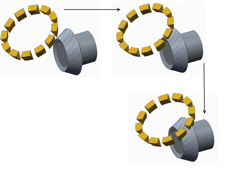
I have made an assembly composed of a gear and hob with gear mechanism (see attachment).
Now I want the hob to remove the material continously when it intersects the gear blank.
I would really appreciate it if anybody can help me.
Best regards
Emanuel
This thread is inactive and closed by the PTC Community Management Team. If you would like to provide a reply and re-open this thread, please notify the moderator and reference the thread. You may also use "Start a topic" button to ask a new question. Please be sure to include what version of the PTC product you are using so another community member knowledgeable about your version may be able to assist.
Labels:
- Labels:
-
Assembly Design
6 REPLIES 6
Dec 21, 2013
05:11 PM
- Mark as New
- Bookmark
- Subscribe
- Mute
- Subscribe to RSS Feed
- Permalink
- Notify Moderator
Dec 21, 2013
05:11 PM
Hello Emanuel and welcome to the forum.
I am going to make two assumptions which you can clarify.
1. You are not using the manufacturing extension
2. You want to show the material removal as an animation
If you only wanted to make the cut, obviously you can do this in many ways, even at the assembly level by making an assembly cut.
To make this an animation, it is more problematic. The difference is that you will be changing the gear which requires regeneration between frames.
Let me know if I'm on the right track and we can look at options.
Dec 21, 2013
11:18 PM
- Mark as New
- Bookmark
- Subscribe
- Mute
- Subscribe to RSS Feed
- Permalink
- Notify Moderator
Dec 21, 2013
11:18 PM
Making the cuts continously is going to end up as an approximation. Intersecting the cutter with the blank at closely spaced steps may be close enough. What is the desired outcome?
Animation of step-by-step cutting is easy enough - either create a trail file that saves a frame after each cut or drive it from AutoIT or similar scripting tool.
Dec 22, 2013
05:19 AM
- Mark as New
- Bookmark
- Subscribe
- Mute
- Subscribe to RSS Feed
- Permalink
- Notify Moderator
Dec 22, 2013
05:19 AM
Above all I want to show the material removal as an animation, but I also want create the true tooth geometry without any gear software.
I have already tried the step-by-step method, but the result is a more ore less rough tooth surface:
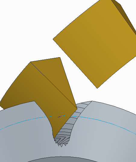
Thank you for the hint with AutoIT.
Best regards
Dec 22, 2013
07:02 AM
- Mark as New
- Bookmark
- Subscribe
- Mute
- Subscribe to RSS Feed
- Permalink
- Notify Moderator
Dec 22, 2013
07:02 AM
Gear teeth profiles still get me but once you get the profile of the hob and the motion that it follows (I'm assuming is it a straight plunge), you can use mechanism to built a series of videos (output as .BMP files) for each depth of the cut you need to make.
Behind the scenes you need a few things:
1. You will be making the cut at varying depth in the assembly. You need to decide how long you want the process for each tooth to take place. This tells you how many frames you need to capture at say 25 frames per second. If you want the full tooth to be cut in 10 seconds, you need 250 frames! You have what... 20 teeth? so that is a 3 minute 20 second video with 5000 frames.
2. Since you know the depth of each cut you can make family tables to cover the depth of each frame. You also have to decide the "cutter speed" if you want to see motion of the hob during each frame. This can be set up with Mechanism so you can go back to your 250 frames and decide how many of those frames will be cutter motion.
The hardest part of the animations is planning the storyboard. What do you need to happened with each frame. I suggest capturing the BMP files and stitching them together after you have them all captured. This makes for the best seamless animation I've found so far. You can run make several captures each with a different depth. If you want to cut all 20 teeth, you will have to rotate the gear (a few frames for that) and do it again.
I know there's got to be an easier way but I can't think of one in core Creo.
Dec 22, 2013
12:42 PM
- Mark as New
- Bookmark
- Subscribe
- Mute
- Subscribe to RSS Feed
- Permalink
- Notify Moderator
Dec 22, 2013
12:42 PM
Thank you Antonius but that's exactly the same method I proceeded.
Unfortunately it is more than inefficient and the result leaves a lot to be desired.
Isn't there any other possibility to solve this problem?
regards
Dec 22, 2013
03:42 PM
- Mark as New
- Bookmark
- Subscribe
- Mute
- Subscribe to RSS Feed
- Permalink
- Notify Moderator
Dec 22, 2013
03:42 PM
I'm going to make one off-beat method that might just work depending on the display mode....
What if you overlay two (or 3) fully developed gears and slowly rotate then away from each other? They would begin to appear solid, and as you spin them "apart", they would appear to be having deeper grooves cut into them. In this method, it is a single mechanism setup for each tooth where the cutter rotates and plunges while the gears follow a custom "indexed" profile.
Again, are you capturing all the teeth being cut, or just a single cut? For the following cuts, you need to modify the "blanking" gear so it doesn't obstruct the previous cut. This reduces the effort from 5000 to 20.
