
Turn on suggestions
Auto-suggest helps you quickly narrow down your search results by suggesting possible matches as you type.
Showing results for
Turn on suggestions
Auto-suggest helps you quickly narrow down your search results by suggesting possible matches as you type.
Showing results for
Community Tip - Learn all about the Community Ranking System, a fun gamification element of the PTC Community. X
- Community
- Creo+ and Creo Parametric
- Analysis
- Adjust model bounding-box for better fit-to-screen...
Options
- Subscribe to RSS Feed
- Mark Topic as New
- Mark Topic as Read
- Float this Topic for Current User
- Bookmark
- Subscribe
- Mute
- Printer Friendly Page
Adjust model bounding-box for better fit-to-screen?
Mar 03, 2016
09:14 AM
- Mark as New
- Bookmark
- Subscribe
- Mute
- Subscribe to RSS Feed
- Permalink
- Notify Moderator
Mar 03, 2016
09:14 AM
Adjust model bounding-box for better fit-to-screen?
Often with top-down assembly the bounding boxes for parts are not representative of the part, and this means that the automatic fit-to-screen function doesn't operate as well as it could. How can I adjust the bounding-box for a part:
a) manually?
b) automatically around all solid geometry?
c) automatically around all geometry?
Thanks
This thread is inactive and closed by the PTC Community Management Team. If you would like to provide a reply and re-open this thread, please notify the moderator and reference the thread. You may also use "Start a topic" button to ask a new question. Please be sure to include what version of the PTC product you are using so another community member knowledgeable about your version may be able to assist.
Labels:
- Labels:
-
General
6 REPLIES 6
Mar 04, 2016
11:46 PM
- Mark as New
- Bookmark
- Subscribe
- Mute
- Subscribe to RSS Feed
- Permalink
- Notify Moderator
Mar 04, 2016
11:46 PM
Nope, editing these values is not possible.
There was a recent change that allows datums to be excluded from the bounding box size calculations.
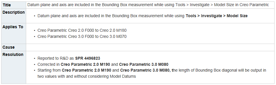
https://support.ptc.com/appserver/cs/view/solution.jsp?n=CS93540
Mar 04, 2016
11:47 PM
- Mark as New
- Bookmark
- Subscribe
- Mute
- Subscribe to RSS Feed
- Permalink
- Notify Moderator
Mar 04, 2016
11:47 PM
If you don't have (or want to go to) these later builds, you can achieve similar results with Toolkit ($$$).
https://support.ptc.com/appserver/cs/view/solution.jsp?n=CS222336
https://support.ptc.com/appserver/cs/view/solution.jsp?n=CS93540
Jul 18, 2016
05:28 PM
- Mark as New
- Bookmark
- Subscribe
- Mute
- Subscribe to RSS Feed
- Permalink
- Notify Moderator
Jul 18, 2016
05:28 PM
It drives me nuts that I have to consider how I define certain datums since they influence how the model is zoomed in on. I currently have a model that I have to re-think because of some stupid arbitrarily rotated plane intersected with the mid-plane gives me the "horizontal" for that sketching plane. but this ends up being horrible because the intersection is 10x the longest dimension away from the default Csys. so when I put the model in perspective, or when I just zoom-all, the model is tiny! it's makin' me bonkers 
Jul 18, 2016
07:44 PM
- Mark as New
- Bookmark
- Subscribe
- Mute
- Subscribe to RSS Feed
- Permalink
- Notify Moderator
Jul 18, 2016
07:44 PM
When you create the datum, click the second tab (also available at redefine) to set the size. You can either drag the extent with drag handles or tell it to fit another feature. Viola - problem solved.
Jul 20, 2016
04:13 AM
- Mark as New
- Bookmark
- Subscribe
- Mute
- Subscribe to RSS Feed
- Permalink
- Notify Moderator
Jul 20, 2016
04:13 AM
unfortunately no, it doesn't solve the problem if moving the bounds of the plane anywhere within it's planar space does not bring it closer to the model, still screwed.
though technically in some cases that could be a work-around.
so here's the basic case - 3 points constrain the curve. the curve is a spline that must be planar and NOT a combined projection for numerous reasons. The configuration below was how it started, a moderate angle, no problem.
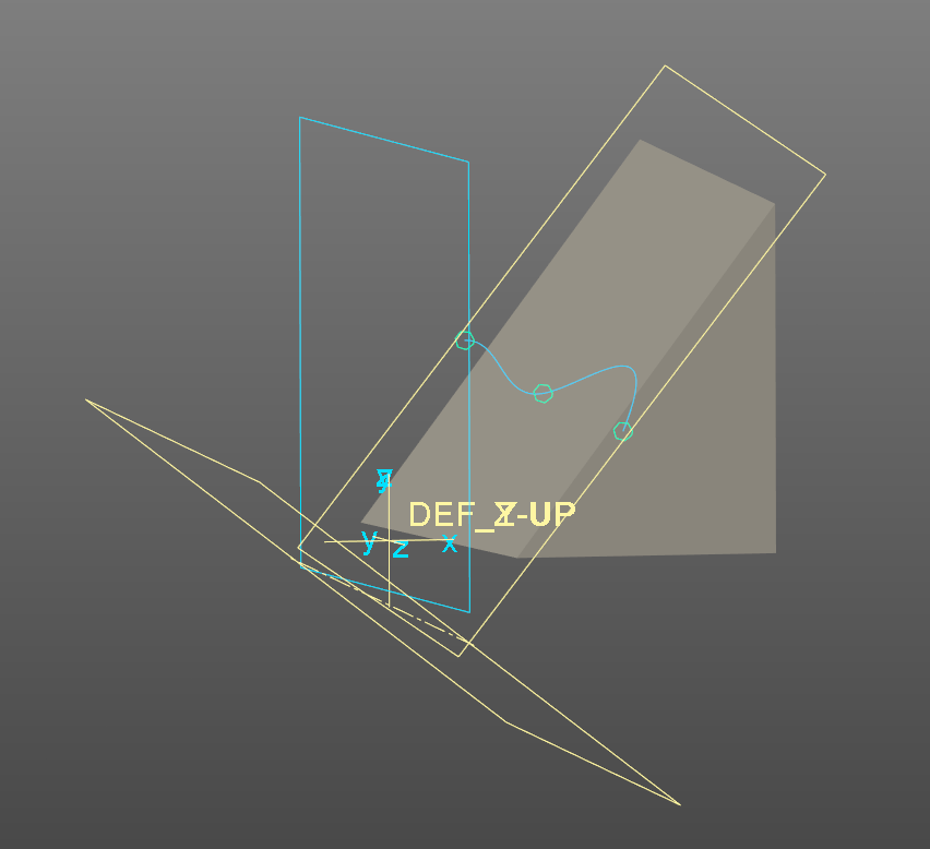
However, adjustments to the design required a much steeper angle, which brought me to the following and this isn't even as bad as it was to be honest.
the final conclusion was to re-define how the sketch plane was constructed entirely. it isn't a problem, it's just tedious extra work for something that shouldn't be included in the bounding box if it's layered off.
bounding box for zoom-extents should be limited to only what is visible!
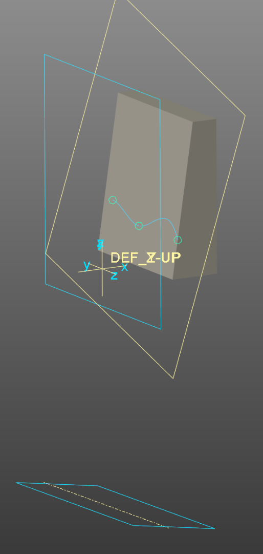
here was the final work-around which doesn't even require any hand-wavy nonsense of adjusting the plane's display-outline (which I'll admit can be very cool at times, but not very well parametric.
in the following 2 examples the horizontal planes are parallel. in the "new way" the plane is always stuck to the datum point but needs an extra datum plane to define it, But it is 100% parallel, and will never cause the bounding box issue.
new way highlighted
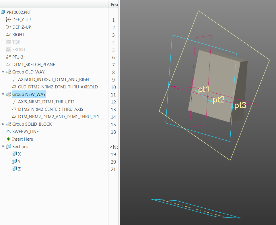
old way highlighted

Jul 20, 2016
04:43 AM
- Mark as New
- Bookmark
- Subscribe
- Mute
- Subscribe to RSS Feed
- Permalink
- Notify Moderator
Jul 20, 2016
04:43 AM
for what it's worth, that display outline is relative to the internal origin of the plane. did you know there was one? yup, there is, and it's relative to how the plane is defined.
when defining a plane by 3 points, the order matters somewhat if you care how your planes are displayed.
I believe the origin of each plane is the first point picked. the second point picked lies on the x-axis, and the third point lies on the positive y side of the x axis. this matters for a number of reasons. automatic sketch orientation for starters. makes a difference how the tangent angle is projected for ISDX curves. oh, if you pick points A B C in counter clockwise direction the plane will face towards you. if you pick the points anti-clockwise the plane will face away from you.
and actually the tangent comes back to the original point which is - even in this example, all the parts of the planes that lay outside the boundary of the 3 points shouldn't necessarily be included in the bounding box. but especially if they are hidden.
Announcements
Top Tags
