
Turn on suggestions
Auto-suggest helps you quickly narrow down your search results by suggesting possible matches as you type.
Showing results for
Turn on suggestions
Auto-suggest helps you quickly narrow down your search results by suggesting possible matches as you type.
Showing results for
Community Tip - Your Friends List is a way to easily have access to the community members that you interact with the most! X
- Community
- Creo+ and Creo Parametric
- Analysis
- Apply Bending Moment to a Shaft
Options
- Subscribe to RSS Feed
- Mark Topic as New
- Mark Topic as Read
- Float this Topic for Current User
- Bookmark
- Subscribe
- Mute
- Printer Friendly Page
Apply Bending Moment to a Shaft
Mar 31, 2024
08:09 PM
- Mark as New
- Bookmark
- Subscribe
- Mute
- Subscribe to RSS Feed
- Permalink
- Notify Moderator
Mar 31, 2024
08:09 PM
Apply Bending Moment to a Shaft

I need the procedure to apply the moment load to this shaft. I cannot find anything on how to do this. I even tried two different AI website to try to find an answer. Neither site gave me an answer. What features? How applied?
Solved! Go to Solution.
Labels:
- Labels:
-
Creo Simulation Live
1 ACCEPTED SOLUTION
Accepted Solutions
Apr 01, 2024
11:22 AM
- Mark as New
- Bookmark
- Subscribe
- Mute
- Subscribe to RSS Feed
- Permalink
- Notify Moderator
Apr 01, 2024
11:22 AM
I think the community is trying to help you educate yourself on this because it is actually a simple problem for someone with a mechanical engineering training. AI has no understanding of TRUTH, it does not even always give its best answer and needs to be "reminded" of key principals to be coached to a correct answer.
I am guessing that you put a load on both ends and are unconstrained. A free body diagram helps but it will not get you to the understanding of using constraints to automatically account for the reaction forces at one of the ends. The drawing you gave actually is a FBD. It is important whenever looking at a problem to consider how a real part would be tested. In this case a real length part will be put in a holding fixture and a torque put on only one of the ends. You need to understand St Venant's principal considering the distance from the area of interest to your boundary conditions. Your model with a torque at both ends could be constrained using what is called inertia relief but it is an unusual and unnecessary approach.
There are many correct ways to do this but I will jump to the answer I would give.

If desired you can check the reaction moment at the constraint end with a measure to prove that it is an equal and opposite moment to the applied load. Another similar reaction force measure can be used to verify that Fx, Fy, Fz ~=0


8 REPLIES 8
Apr 01, 2024
08:25 AM
- Mark as New
- Bookmark
- Subscribe
- Mute
- Subscribe to RSS Feed
- Permalink
- Notify Moderator
Apr 01, 2024
08:25 AM
Creo does have help files available, did you look at the documentation?
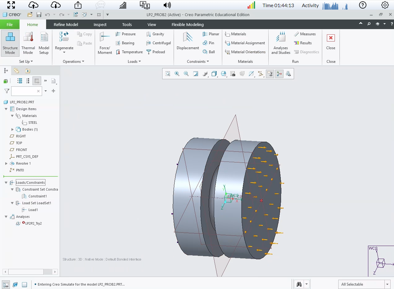
When you click Home >Force/Moment, the Force/Moment Load dialog box opens.
For Creo Simulate: Moment—Specify the magnitude and direction of the moment for your load. Note that moment loads should only be applied to moment capable references such as shells or beams, or the type of Distribution must be Total Load at Point.Select the units of moment from the drop-down list or accept the default units.
========================================
Involute Development, LLC
Consulting Engineers
Specialists in Creo Parametric
Involute Development, LLC
Consulting Engineers
Specialists in Creo Parametric
Apr 01, 2024
10:04 AM
- Mark as New
- Bookmark
- Subscribe
- Mute
- Subscribe to RSS Feed
- Permalink
- Notify Moderator
Apr 01, 2024
10:04 AM
I've spent hours and hours over the past 4 days trying to find the "Total Load at Point". I even queried CoPilot and Open AI Chat GPT. (Not helpful!)
I finally found it last night. Then I still had to guess at how to setup the moment load. None of the information shows a step-by-step of how to do it. It should not be this hard to figure out how to do this. This loading situation is one of the most common for all shafts!!
I completed the analysis, at Pass 8 it died saying the model is not properly constrained. Back to the drawing board I go! 😞
Apr 01, 2024
10:10 AM
- Mark as New
- Bookmark
- Subscribe
- Mute
- Subscribe to RSS Feed
- Permalink
- Notify Moderator
Apr 01, 2024
10:10 AM
I would suggest using a pencil/paper (or equivalent) to draw the free body diagram of this problem. Upload the picture of the shaft, supports, loads, etc. This is essential to defining the boundary conditions for any simulation input. There is usually more than one way to set the problem up for FEA and details matter here. With the FBD, share the sim model with boundary conditions you attempted in Creo that is not solving.
========================================
Involute Development, LLC
Consulting Engineers
Specialists in Creo Parametric
Involute Development, LLC
Consulting Engineers
Specialists in Creo Parametric
Apr 01, 2024
11:22 AM
- Mark as New
- Bookmark
- Subscribe
- Mute
- Subscribe to RSS Feed
- Permalink
- Notify Moderator
Apr 01, 2024
11:22 AM
I think the community is trying to help you educate yourself on this because it is actually a simple problem for someone with a mechanical engineering training. AI has no understanding of TRUTH, it does not even always give its best answer and needs to be "reminded" of key principals to be coached to a correct answer.
I am guessing that you put a load on both ends and are unconstrained. A free body diagram helps but it will not get you to the understanding of using constraints to automatically account for the reaction forces at one of the ends. The drawing you gave actually is a FBD. It is important whenever looking at a problem to consider how a real part would be tested. In this case a real length part will be put in a holding fixture and a torque put on only one of the ends. You need to understand St Venant's principal considering the distance from the area of interest to your boundary conditions. Your model with a torque at both ends could be constrained using what is called inertia relief but it is an unusual and unnecessary approach.
There are many correct ways to do this but I will jump to the answer I would give.
If desired you can check the reaction moment at the constraint end with a measure to prove that it is an equal and opposite moment to the applied load. Another similar reaction force measure can be used to verify that Fx, Fy, Fz ~=0
Apr 06, 2024
10:50 AM
- Mark as New
- Bookmark
- Subscribe
- Mute
- Subscribe to RSS Feed
- Permalink
- Notify Moderator
Apr 06, 2024
10:50 AM
Not being testy at all here. However, I am teaching a class on this and my knowledge of how to do all this is very limited. Thanks for taking the time to answer. Your solution is correct!
Apr 08, 2024
10:49 AM
- Mark as New
- Bookmark
- Subscribe
- Mute
- Subscribe to RSS Feed
- Permalink
- Notify Moderator
Apr 08, 2024
10:49 AM
No Problem. Hopefully I did not sound disrespectful myself. I have a high regard for those willing and patient enough to teach others.
Apr 03, 2024
04:54 AM
- Mark as New
- Bookmark
- Subscribe
- Mute
- Subscribe to RSS Feed
- Permalink
- Notify Moderator
Apr 05, 2024
08:06 AM
- Mark as New
- Bookmark
- Subscribe
- Mute
- Subscribe to RSS Feed
- Permalink
- Notify Moderator
Apr 05, 2024
08:06 AM
Hello @tfilipiak,
It looks like you have some responses from some community members on your topic . If any of these replies helped you solve your question please mark the appropriate reply as the Accepted Solution.
Of course, if you have more to share on your issue, please let the Community know so other community members can continue to help you.
Thanks,
Community Moderation Team.
Announcements
Top Tags
