
Turn on suggestions
Auto-suggest helps you quickly narrow down your search results by suggesting possible matches as you type.
Showing results for
Turn on suggestions
Auto-suggest helps you quickly narrow down your search results by suggesting possible matches as you type.
Showing results for
Community Tip - Visit the PTCooler (the community lounge) to get to know your fellow community members and check out some of Dale's Friday Humor posts! X
- Community
- Creo (Previous to May 2018)
- Creo Modeling Questions
- Degrees of Freedom: Why 6? Why 3?
Options
- Subscribe to RSS Feed
- Mark Topic as New
- Mark Topic as Read
- Float this Topic for Current User
- Bookmark
- Subscribe
- Mute
- Printer Friendly Page
Degrees of Freedom: Why 6? Why 3?
Sep 19, 2013
12:11 PM
- Mark as New
- Bookmark
- Subscribe
- Mute
- Subscribe to RSS Feed
- Permalink
- Notify Moderator
Sep 19, 2013
12:11 PM
Degrees of Freedom: Why 6? Why 3?
In Wildfire 5.0, users were allowed to apply distributed moments over the faces of solid parts, as shown in this simple beam model.
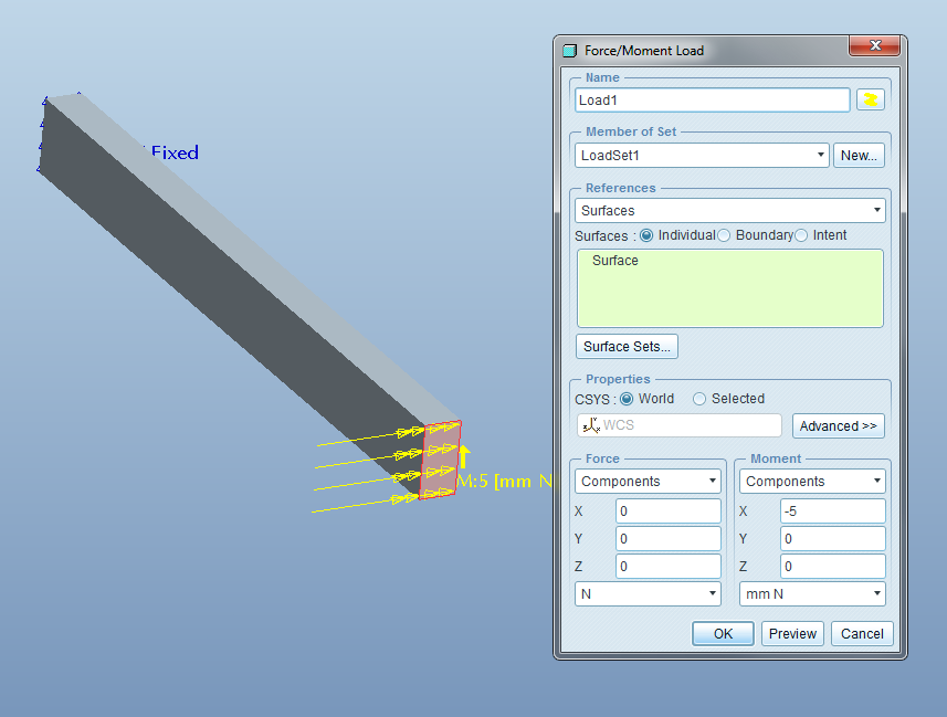
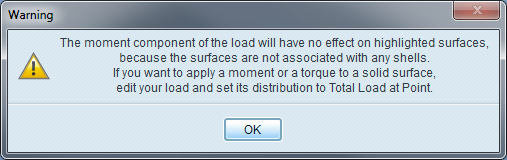
In reality, such a load has no physical meaning, and if you defined such a load, Mechanica (now called Creo Simulate) would let you know with this warning message.
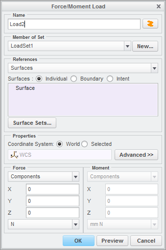
In Creo Simulate 1.0, users are no longer allowed to create such loads, as indicated by the inactive moment area of the newer Force/Moment dialog.
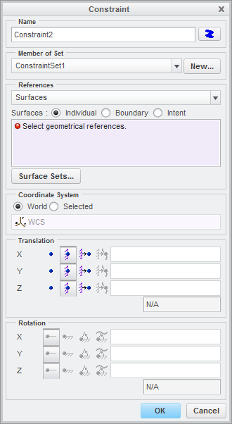
Analogous changes were made to the Constraint dialog as well.
Some Simulate users were confused by this change and wondered if some of the existing functionality had been removed from the product. The goal of this post is to explain why we made this change and to help users employ other methods to apply moment loads to their modes.
Most mechanical and structural engineers were introduced to the theory of beams during a strength of materials class early in in their undergraduate education. In that class, we learned that for long and slender beams, we make a kinematic assumption, that cross sections perpendicular the beam’s neutral axis generally remains planar and perpendicular to that axis. With this observation, we are able to describe the deformation of a three dimensional beam as the deflection, w, of the neutral axis. The governing equation of an Euler-Bernoulli beam that deforms in a plane is a simple fourth order ordinary differential equation,
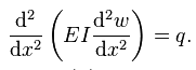
where q is a distributed load per unit length along the beam and x is a measure of length along the beam’s neutral axis. This equation can be solved by simple integration, and the resulting four constants can be determined from the boundary conditions, two at each end of the beam. To specify the boundary conditions, at each end of the beam, either the deflection or the shear force must be given, and either the slope/rotation (dw/dx) or the moment must be given. Thus, if there is no load on the beam, its shape is determined by both the deflection and rotation at each end of the beam. The deflection and rotation are considered to be “degrees of freedom” of a beam.
Here’s a figure from http://www.colorado.edu/engineering/cas/courses.d/IFEM.d/IFEM.Ch12.d/IFEM.Ch12.pdf, showing the two degrees of freedom (v & theta) at each end of the beam. (v in this figure corresponds to w in the above equation.)
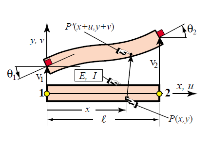
For a more general planar beam, that can also stretch (due to an applied axial force) and twist (due to an applied axial moment), the governing equation is slightly more complicated and results in a beam formation with four degrees of freedoms (two displacements and two rotations). A beam that can deflect out of plane has six degrees of freedom: three displacements and three rotations. Hence, beams in 3D models in Creo Simulate have 6 degrees of freedom: three displacements and 3 rotations.
Similarly, shells idealize thin structures. In this case, the essential kinematic assumption is that line segments that are initially normal to the midsurface of the shell remain straight and normal (or nearly normal). Thus, the deformation of a three dimensional shell can be described by the deformation of the midsurface and the governing equation (in this case, a fourth order partial differential equation) can be solved if boundary conditions are specified. For shells deforming in a 3D space, the boundary conditions are either displacements or forces per unit length and rotations or moments per unit length. Thus, like a beam, a shell in Creo Simulate has 6 degrees of freedom.*
Because beams and shells have six degrees of freedom, it is possible to prescribe displacements or forces (per unit length for shells) and rotations or moments (per unit length for shells) on their boundaries. Also, for a beam, displacements or forces per unit length and rotations or moments per unit length can be specified along the length of its neutral axis; for a shell, displacements or forces per unit area and rotations or moments per unit area can be specified over the area of the midsurface.
In contrast to beams and shells, the governing equations of a continuum solid are much simpler (perhaps ironically) because there is no simplifying kinematic assumption. The governing equation for a continuum solid is a second order partial differential equation, which can be solved if either displacement or traction boundary conditions are specified. Thus, a continuum solid has only three degrees of freedom, corresponding to the three components of displacement. As such, it is not possible to specify either rotations or moments per unit area over the boundary of continuum solids.
The above is a short explanation of why distributed moments can be applied to beams and shells but not to solids. Of course, there are many times when engineers want to apply a moment to the boundary of a solid. One of the goals of this blog post was to explain how to do that, but this post is already too long, so that will have to wait until next time. The preview hints are “total load at point” and “weighted links.” (Look it up in Creo Simulate’s online documentation if you can’t wait.)
*In fact, the hand waving argument given above leads to a shell formulation with 5 degrees a freedom. In Creo Simulate, a sixth “drilling” degree of freedom, is added to the formulation and is tied to the in-plane displacements.
References:
- Variational Formulation of Plane Beam Element: http://www.colorado.edu/engineering/cas/courses.d/IFEM.d/IFEM.Ch12.d/IFEM.Ch12.pdf
- Finite Element Formulations for Beams (Dr. Fehmi Cirak): http://www-g.eng.cam.ac.uk/csml/teaching/4d9/4D9_handout2.pdf
- Linear Elasticity, Wikipedia: http://en.wikipedia.org/wiki/Linear_elasticity
2 REPLIES 2
Sep 23, 2013
04:34 AM
- Mark as New
- Bookmark
- Subscribe
- Mute
- Subscribe to RSS Feed
- Permalink
- Notify Moderator
Sep 23, 2013
04:34 AM
That's a really sensible change. I always find myself explaining to new users how the rotation constraints actually do nothing (for a 3D solid mesh) because points only know about translation.
Presumably, in the load dialog at least, the Moment section becomes re-activated if you change to Total Load At Point?
Sep 23, 2013
11:47 AM
- Mark as New
- Bookmark
- Subscribe
- Mute
- Subscribe to RSS Feed
- Permalink
- Notify Moderator
Sep 23, 2013
11:47 AM
Jonathan,
I'm glad you like the change.
Yes, if the load is a Total Load at Point, then the moment section is re-activated.
Tad Doxsee
PTC
