
Turn on suggestions
Auto-suggest helps you quickly narrow down your search results by suggesting possible matches as you type.
Showing results for
Turn on suggestions
Auto-suggest helps you quickly narrow down your search results by suggesting possible matches as you type.
Showing results for
Community Tip - Need to share some code when posting a question or reply? Make sure to use the "Insert code sample" menu option. Learn more! X
- Community
- Creo (Previous to May 2018)
- Creo Modeling Questions
- Sketcher Accuracy
Options
- Subscribe to RSS Feed
- Mark Topic as New
- Mark Topic as Read
- Float this Topic for Current User
- Bookmark
- Subscribe
- Mute
- Printer Friendly Page
Sketcher Accuracy
Jan 04, 2016
04:08 PM
- Mark as New
- Bookmark
- Subscribe
- Mute
- Subscribe to RSS Feed
- Permalink
- Notify Moderator
Jan 04, 2016
04:08 PM
Sketcher Accuracy
Creo 2, M160 (I also tried Creo 3, M070 with the same results)
I have a sketch consisting of a single arc and I want to control the length of the arc, not the radius. I've constrained the ends and I've tried adding a perimeter dim or adding a chord dim by selecting the arc, one end, the other and then middle button. Creo won't let me add the dim, it thinks the dims are too small. I get an error "Please increase the number of digits" or something about sketcher accuracy.
I can get it to add the perimeter dim, and I tell it to vary a linear dim that is 0.002", however it flattens out the arc to it's maximum length and turns my 0.002" dim to 1148.477". The sketch is then locked up and unchangeable.
There used to be a setting for sketcher accuracy, but I cannot find it. Does that still exist? If not, how do I get Creo to accept this perimeter dim?
I cannot share the model due to client confidentiality.
Solved! Go to Solution.
1 ACCEPTED SOLUTION
Accepted Solutions
Jan 04, 2016
05:28 PM
- Mark as New
- Bookmark
- Subscribe
- Mute
- Subscribe to RSS Feed
- Permalink
- Notify Moderator
Jan 04, 2016
05:28 PM
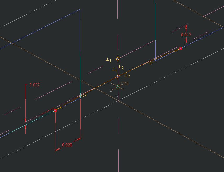
Sketcher accuracy is defined by increasing the number of decimals places. File->options->sketcher->Accuracy and sensitivity. By increasing the decimal places I was able to set the .002 dim to vary and rotate HINGE_1 datum to 90 deg. I did have to recreate the dimension after setting the number of decimal places. Is this what you're looking for? Not sure if an arc length dimension is supposed to show up in Creo though. I don't use perimeter dims much these days.
Also this tip is OLD, but probably still helpful.
19 REPLIES 19
Jan 04, 2016
04:27 PM
- Mark as New
- Bookmark
- Subscribe
- Mute
- Subscribe to RSS Feed
- Permalink
- Notify Moderator
Jan 04, 2016
04:27 PM
I was able to create a simple model that illustrates the issue, it's attached.
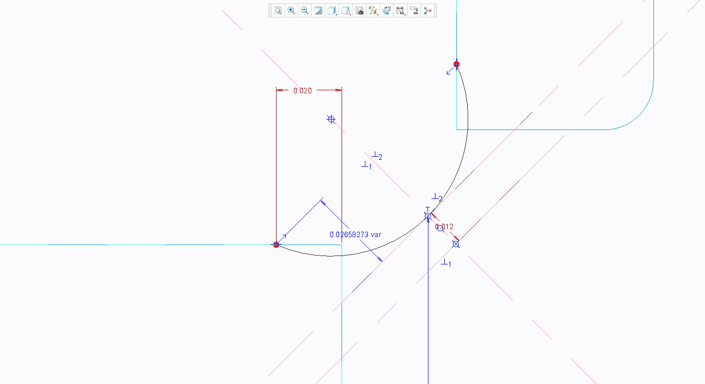
In "Sketch 3", shown below, try to create a perimeter dim and set the 0.002" dim to vary. This is a living hinge part, I need the length of this sketch to be constant while the hinge angle (HINGE_1 plane) varies.
Jan 04, 2016
04:55 PM
- Mark as New
- Bookmark
- Subscribe
- Mute
- Subscribe to RSS Feed
- Permalink
- Notify Moderator
Jan 04, 2016
04:55 PM
Why not dimension the arc with an arc-length rather than perimeter?

I am not clear on your constraints but I removed the vertical reference since the .020 (.030 above) was still fixed. I am not sure what you are considering the "fixed" end/center for your movement. Above is Creo 3.0 M020.
Jan 04, 2016
05:05 PM
- Mark as New
- Bookmark
- Subscribe
- Mute
- Subscribe to RSS Feed
- Permalink
- Notify Moderator
Jan 04, 2016
05:05 PM
You might have found a bug, Doug. In Creo 3.0 M020, I am able to make that dimension without issue directly in your file...
Perimeter dim (click arc); place dim; select .002 as ref; go hunt down the end of the 10-mile leader to find the perimeter dim.
I've attached the file in case you decide to create a support case.

Jan 05, 2016
08:22 AM
- Mark as New
- Bookmark
- Subscribe
- Mute
- Subscribe to RSS Feed
- Permalink
- Notify Moderator
Jan 05, 2016
08:22 AM
Odd, I tried it in Creo 3 M070 and it would not work.
Jan 04, 2016
05:09 PM
- Mark as New
- Bookmark
- Subscribe
- Mute
- Subscribe to RSS Feed
- Permalink
- Notify Moderator
Jan 04, 2016
05:09 PM
I'm trying to get a more accurate visual representation of the hinge when folded. Keeping the arc length consistent makes the folded hinge look right. In hindsight, this should have been done with a spinal bend, but I think I'm too far along to redefine this now.
The "vertical" C/L is defined through the axis that the hinge is assumed to pivot on and symmetric about the corners of the two bodies. So it tilts as the hinge is bent and needs to be able to be an any angle, so no vertical or horizontal constraints work. The upper point (in my image) represents the thickness of the living hinge.
An arc length dim would work but the nice thing about a perimeter dim is that you can choose what other dim to allow to vary. In this case, I want the "depth" of the arc (the 0.002" dim) t ovary as the sketch "bends". I couldn't get Creo to let me remove that one when i created the arc length dim.
I've pretty much given up and created a sketch that works, but isn't quite accurate when "bent". The flat is more important for making the mold anyway. I'd love to know how to get this to work, however.
Jan 04, 2016
05:36 PM
- Mark as New
- Bookmark
- Subscribe
- Mute
- Subscribe to RSS Feed
- Permalink
- Notify Moderator
Jan 04, 2016
05:36 PM
This can also be accomplished with a spinal bend feature, but if I recall it can be a bit fussy to setup.
Jan 05, 2016
08:20 AM
- Mark as New
- Bookmark
- Subscribe
- Mute
- Subscribe to RSS Feed
- Permalink
- Notify Moderator
Jan 05, 2016
08:20 AM
You're right, and in hindsight I think that may have been a better approach. I'm very close to rebuilding it with a spinal bend in mind.
Part of the challenge there is that there are two living hinges in this part, 90 degrees from each other, and each needs to bend 0, 90 and 180 degrees. I'll need a family table showing at least 3 states, open (as molded), fully closed (both at 180) and an interim state (both at 90). I'm thinking that may mean 4 spinal bends that get turned on or off based on the desired state. I'm not sure I can create the features in such a way that they will work independent of one another.
Jan 04, 2016
05:47 PM
- Mark as New
- Bookmark
- Subscribe
- Mute
- Subscribe to RSS Feed
- Permalink
- Notify Moderator
Jan 04, 2016
05:47 PM
That makes more sense. The only limitation that bugs me in Creo sketch is that you can only create one perimeter dim.
There are so many dynamics going on flexures that modeling it can really distract from the actual physics. My preference in these cases is to link with splines. Now I can manage input angles and length. Splines also have the ability to go "over center(?)" where you cannot reverse an arc (arc up/linear/arc down) dynamically.
The other thing about flexures... typically... is that you have a ground body on one side and moving body on the other. This is where your sketch concept varies.
Jan 05, 2016
08:16 AM
- Mark as New
- Bookmark
- Subscribe
- Mute
- Subscribe to RSS Feed
- Permalink
- Notify Moderator
Jan 05, 2016
08:16 AM
The other side of this living hinge (not included in my demonstration model) is made with a spline for that reason.
Jan 04, 2016
05:28 PM
- Mark as New
- Bookmark
- Subscribe
- Mute
- Subscribe to RSS Feed
- Permalink
- Notify Moderator
Jan 04, 2016
05:28 PM
Sketcher accuracy is defined by increasing the number of decimals places. File->options->sketcher->Accuracy and sensitivity. By increasing the decimal places I was able to set the .002 dim to vary and rotate HINGE_1 datum to 90 deg. I did have to recreate the dimension after setting the number of decimal places. Is this what you're looking for? Not sure if an arc length dimension is supposed to show up in Creo though. I don't use perimeter dims much these days.
Also this tip is OLD, but probably still helpful.
Jan 05, 2016
08:37 AM
- Mark as New
- Bookmark
- Subscribe
- Mute
- Subscribe to RSS Feed
- Permalink
- Notify Moderator
Jan 05, 2016
08:37 AM
That's the setting I was looking for, I think. However, it's a little misleading in the options dialog. It sets the config option def_dec_places which affects all dims, not just sketcher. So, all feature dims plus all created drawing dims now become 4 places. There used to be a separate option for sketcher dims only, which is really what I need.
Also, while I was able to create the dim, it wouldn't fold to 180 degrees anyway. Back to the drawing board, I guess.
Jan 05, 2016
09:20 AM
- Mark as New
- Bookmark
- Subscribe
- Mute
- Subscribe to RSS Feed
- Permalink
- Notify Moderator
Jan 05, 2016
09:20 AM
BTW - I did discover that you can change that setting, not save it to a config file and then change it back and the perimeter dim will stay at 4 places and still work.
I'm currently working through changing the model to a spinal bend, though, because Creo can't keep all the constraints as it folds over 180 degrees.
Jan 05, 2016
10:14 AM
- Mark as New
- Bookmark
- Subscribe
- Mute
- Subscribe to RSS Feed
- Permalink
- Notify Moderator
Jan 05, 2016
10:14 AM
Set the config option sketcher_dec_places for sketcher dims only
Jan 05, 2016
10:18 AM
- Mark as New
- Bookmark
- Subscribe
- Mute
- Subscribe to RSS Feed
- Permalink
- Notify Moderator
Jan 05, 2016
10:18 AM
ok nevermind they removed that a while ago
Jan 05, 2016
10:59 AM
- Mark as New
- Bookmark
- Subscribe
- Mute
- Subscribe to RSS Feed
- Permalink
- Notify Moderator
Jan 05, 2016
10:59 AM
Easy fix - just don't create driven dimensions in the drawing! ha...
Jan 05, 2016
11:39 AM
- Mark as New
- Bookmark
- Subscribe
- Mute
- Subscribe to RSS Feed
- Permalink
- Notify Moderator
Jan 05, 2016
11:39 AM
Let's not start that debate again. 
Jan 04, 2016
05:43 PM
- Mark as New
- Bookmark
- Subscribe
- Mute
- Subscribe to RSS Feed
- Permalink
- Notify Moderator
Jan 04, 2016
05:43 PM
Oh yeah, tracked down the perim dimension. I'm using Creo 3.0 M030 and was not able to create the perimeter dim without increacing sketcher accuracy.
Jan 04, 2016
08:58 PM
- Mark as New
- Bookmark
- Subscribe
- Mute
- Subscribe to RSS Feed
- Permalink
- Notify Moderator
Jan 04, 2016
08:58 PM
Jeremy, you're right. Setting this to 4 places (my default) lets the perimeter dim work as expected.
Creo 3 M020 also failed with sketcher decimal places set to 2.
Jan 04, 2016
07:59 PM
- Mark as New
- Bookmark
- Subscribe
- Mute
- Subscribe to RSS Feed
- Permalink
- Notify Moderator
Jan 04, 2016
07:59 PM
This is where the curvature element would be handy. Fixed length an the inverse radius so it can go from 0 to +/- values to bend each way, where 0 = perfectly straight.
