
Turn on suggestions
Auto-suggest helps you quickly narrow down your search results by suggesting possible matches as you type.
Showing results for
Turn on suggestions
Auto-suggest helps you quickly narrow down your search results by suggesting possible matches as you type.
Showing results for
Community Tip - You can change your system assigned username to something more personal in your community settings. X
- Community
- Creo+ and Creo Parametric
- Customization
- 5-sided machining in Pro/E
Options
- Subscribe to RSS Feed
- Mark Topic as New
- Mark Topic as Read
- Float this Topic for Current User
- Bookmark
- Subscribe
- Mute
- Printer Friendly Page
5-sided machining in Pro/E
Oct 25, 2011
03:43 PM
- Mark as New
- Bookmark
- Subscribe
- Mute
- Subscribe to RSS Feed
- Permalink
- Notify Moderator
Oct 25, 2011
03:43 PM
5-sided machining in Pro/E
Dear Pro/Gurus,
Recently I faced a problem that I haven't considered it as an issue in the
past.
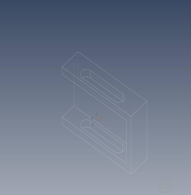
On a 5-axis c.n.c machine I wanted to machine the 3 sides of a block with
the same coordinate system.
In X-Y plane I would remove the open pocket, and in Y-Z plane (B- , B+) the
two slots.
Apart from surface machining - profile and swarf mill that can be used for
finishing,
none of the rest Pro/e sequences can provide a rough milling in 5 axis.
Not even a face milling.
How can I rough the two opposite slots when Pro/e dos not support volume
milling or surface window in 5 axes?
One would think that I should create and select a different coordinate
system for each side;
But this is a waste of time and more over, risky to do it.
I know NX Unigraphics supports 5-sided machining. (roughing - reroughing
etc. )
Any idea of how can I overcome this?
This thread is inactive and closed by the PTC Community Management Team. If you would like to provide a reply and re-open this thread, please notify the moderator and reference the thread. You may also use "Start a topic" button to ask a new question. Please be sure to include what version of the PTC product you are using so another community member knowledgeable about your version may be able to assist.
Labels:
- Labels:
-
General
2 REPLIES 2
Oct 25, 2011
03:57 PM
- Mark as New
- Bookmark
- Subscribe
- Mute
- Subscribe to RSS Feed
- Permalink
- Notify Moderator
Oct 25, 2011
03:57 PM
You create a CYS on each side or face of the part. You then select that CYS for the given NC sequence. The CYS you select is only for tool orientation. The Z direction of the CYS you create must be parallel with the axis of the tool. In your parameters for the given sequence you will see the option for output_coordinate. The default is machine_cys. You want to leave that set to machine_cys. The other option is sequence_cys which would output from the CYS that you just created and not your machine CYS which I assume is you rotational point.
Regards,
Dean
Regards,
Dean
Oct 26, 2011
01:42 AM
- Mark as New
- Bookmark
- Subscribe
- Mute
- Subscribe to RSS Feed
- Permalink
- Notify Moderator
Oct 26, 2011
01:42 AM
Thanks Dean for your immediate response.
I selected the option machine sys in the parameters file and it actually worked.
Best regards,
Dean Dancer <ddancer@hutchinsoninc.com> wrote:
> You create a CYS on each side or face of the part. You then select that CYS for the given NC sequence. The CYS you select is only for tool orientation. The Z direction of the CYS you create must be parallel with the axis of the tool. In your parameters for the given sequence you will see the option for output_coordinate. The default is machine_cys. You want to leave that set to machine_cys. The other option is sequence_cys which would output from the CYS that you just created and not your machine CYS which I assume is you rotational point.
>
> Regards,
>
> Dean
>
Announcements
Top Tags
