
Turn on suggestions
Auto-suggest helps you quickly narrow down your search results by suggesting possible matches as you type.
Showing results for
Turn on suggestions
Auto-suggest helps you quickly narrow down your search results by suggesting possible matches as you type.
Showing results for
Community Tip - If community subscription notifications are filling up your inbox you can set up a daily digest and get all your notifications in a single email. X
- Community
- Creo+ and Creo Parametric
- Customization
- Can anyone help with offset parting line using Cre...
Options
- Subscribe to RSS Feed
- Mark Topic as New
- Mark Topic as Read
- Float this Topic for Current User
- Bookmark
- Subscribe
- Mute
- Printer Friendly Page
Can anyone help with offset parting line using Creo 3.0?
Apr 15, 2016
11:29 AM
- Mark as New
- Bookmark
- Subscribe
- Mute
- Subscribe to RSS Feed
- Permalink
- Notify Moderator
Apr 15, 2016
11:29 AM
Can anyone help with offset parting line using Creo 3.0?
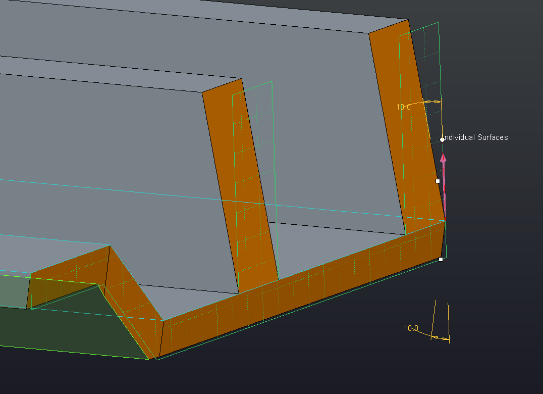
We have a requirement for a plastic part with an offset parting line. In WF 5.0, the draft hinge was just a simple curve drawn normal to the pull direction. Select your draft surfaces, then the curve for the draft hinge, split the draft and select the pull direction and you were done. Can't seem to get it to work in Creo 3.0. Attached is a part with the draft hinge defined by Sketch 1 (also defined by Extrude 12, which is a quilt). Any suggestions on what needs to be done?
Thanks, Tom C.
This thread is inactive and closed by the PTC Community Management Team. If you would like to provide a reply and re-open this thread, please notify the moderator and reference the thread. You may also use "Start a topic" button to ask a new question. Please be sure to include what version of the PTC product you are using so another community member knowledgeable about your version may be able to assist.
Labels:
- Labels:
-
General
6 REPLIES 6
Apr 19, 2016
12:10 PM
- Mark as New
- Bookmark
- Subscribe
- Mute
- Subscribe to RSS Feed
- Permalink
- Notify Moderator
Apr 19, 2016
12:10 PM
I'm not able to open the part since I'm using Creo 2, but I reproduced this area of the part and was able to draft off of a sketch like you're trying to do. Without looking at the actual part it's hard to say what the problem is.
You say the sketched hinge is driven by a quilt - have you tried using the quilt as the draft hinge? I was able to do this too.
Apr 19, 2016
01:55 PM
- Mark as New
- Bookmark
- Subscribe
- Mute
- Subscribe to RSS Feed
- Permalink
- Notify Moderator
Apr 20, 2016
10:33 AM
- Mark as New
- Bookmark
- Subscribe
- Mute
- Subscribe to RSS Feed
- Permalink
- Notify Moderator
Apr 20, 2016
10:33 AM
Thanks Andrew and Matt. I had been able to get the same results as you, but the draft wall had 3 facets to it, which I could not explain. The wall should be an unbroken surface. With that said, further attempts yielded a correct solution. I used split draft by object, not by hinge, using the quilt as the split object. This method produced the unbroken wall. Also, I was able to select all the walls requiring draft in one operation. I did have to do some tweaks to get the chamfers to terminate at the surface edge, but that was expected. I don't know why the sketched curve did not work like WF 5.0, but at least we now have a workable method. Attached is the updated model.
Thanks again, Tom C.
Apr 21, 2016
10:59 AM
- Mark as New
- Bookmark
- Subscribe
- Mute
- Subscribe to RSS Feed
- Permalink
- Notify Moderator
Apr 21, 2016
10:59 AM
Three facets is to be expected when using a curve as the draft hinge.
Creo will "pivot" the surface at every point where it intersects with the draft hinge, In the case of a planar hinge, it's at the theoretical intersection of the drafted surface and the planar hinge. With a curve, that curve must lie on the drafted surface and the "pivot" happens at every point along that curve. At each vertex in the curve changes, new facets are created.
Think of the draft hinge as the part of the surface that will stay in the same position, the rest of the surface will move to create the desired draft angle.
Using a split object isn't what eliminated the facets, it's that it forced you to use a planar draft hinge. Keep in mind that a planar draft hinge with a non planar parting line will change your part size because some part of the surface will have to grow to create the draft.
Apr 21, 2016
11:23 AM
- Mark as New
- Bookmark
- Subscribe
- Mute
- Subscribe to RSS Feed
- Permalink
- Notify Moderator
Apr 21, 2016
11:23 AM
Thanks Doug, that explains things. As mentioned above, I did realize the part size would change using a planer draft hinge, I was more interested in keeping the wall planer for the toolmaker, less effort in making the electrodes. The extra thickness at the bottom of the wall is only a few thousandths, as this part is very small, so no issue there.
Thanks again,
Tom C.
Apr 21, 2016
04:42 PM
- Mark as New
- Bookmark
- Subscribe
- Mute
- Subscribe to RSS Feed
- Permalink
- Notify Moderator
Apr 21, 2016
04:42 PM
Glad to help. There's a lot you can do with the draft tool and some of the options aren't immediately obvious.
Announcements
Top Tags
