
Turn on suggestions
Auto-suggest helps you quickly narrow down your search results by suggesting possible matches as you type.
Showing results for
Turn on suggestions
Auto-suggest helps you quickly narrow down your search results by suggesting possible matches as you type.
Showing results for
Community Tip - You can subscribe to a forum, label or individual post and receive email notifications when someone posts a new topic or reply. Learn more! X
- Community
- Creo+ and Creo Parametric
- Manufacturing (CAM)
- Modeling a globoidal cam
Options
- Subscribe to RSS Feed
- Mark Topic as New
- Mark Topic as Read
- Float this Topic for Current User
- Bookmark
- Subscribe
- Mute
- Printer Friendly Page
Modeling a globoidal cam
Jul 12, 2016
01:14 AM
- Mark as New
- Bookmark
- Subscribe
- Mute
- Subscribe to RSS Feed
- Permalink
- Notify Moderator
Jul 12, 2016
01:14 AM
Modeling a globoidal cam
Hi all,
what I'm trying to do is the same cam you can see in this youtube video.
I have the motion law I want to assign to the rotation of the tower in function of the rotation of the cam.
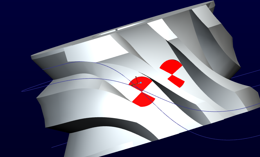
In Mechanism environment, I've made the trace curves of some points of the roller that I've used to cut the cam with surfaces or variable section sweep.
For now, I've tried only one roller cut (three in total).
The cut was decent but there were points where I have interpenetration between cam and roller; especially at the start and the end of the cut.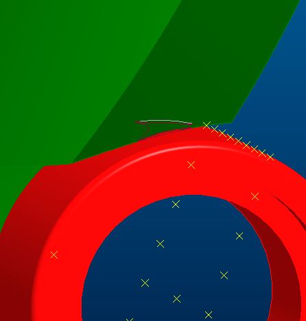

So I've thinked that I had to rotate the plane of the roller where I've put the points for the trace curves. The situation was better but the motion law I've assigned to the roller was random: a sinusoidal law, as the main one, that at the half reverses the direction (otherwise the cut plane too on itself).
But, which is the right motion law to assign to the cut plane of the roller?
How would you have done?
Would you know tell me where can I find more detailed informations about this kind of 3D modeling?
I searched on the web, but I've not found nothing if not videos like what I've attached where, however, you can't see HOW to do it.
Thanks.
Bye
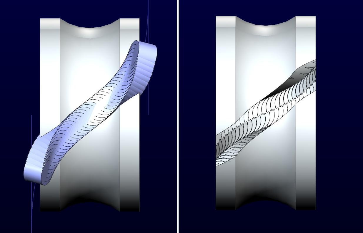
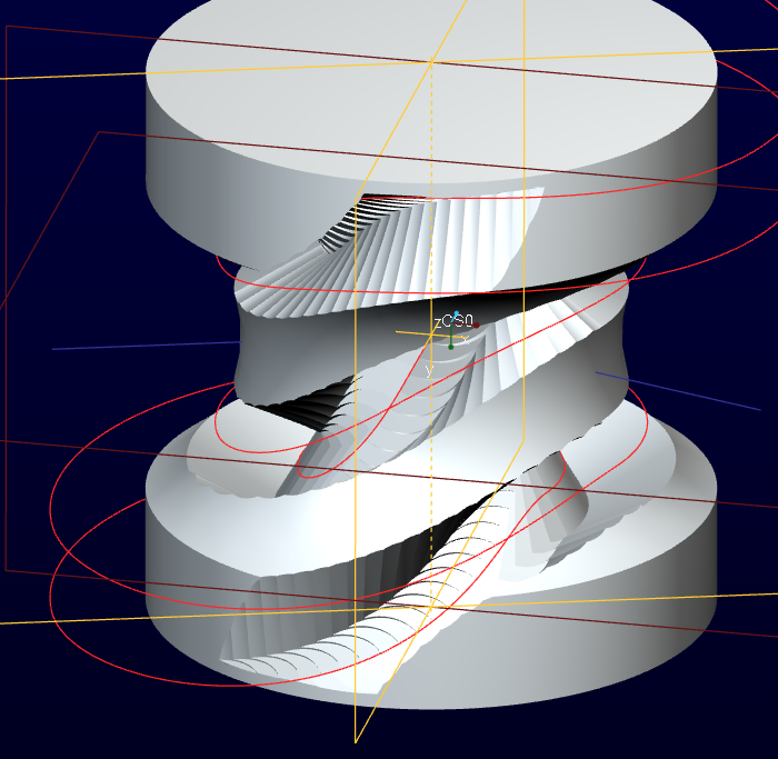
It is very problematic creating features such as this accurately. You can confirm this by patterning the revolved shape of the tool along the path. You will see that often, the profile is different.
This is much the same a gear hob. The helix on the hob are flat yet the result is an involute.
Try creating a centerline spline through the profile. Place a point along that curve. Now pattern that point along that curve. Then set the 1st point to along=0. Create a revolve cut the diameter of the groove width. Use the point pattern to pattern the cut. If all went well, the pattern will follow the normal of the spline which also follows the normal of how it was created.
I have attached an example of why there is a difference.
This is a comparison with the cutting tool patterned through the groove.
You would have to shape your sweep to make sure you fully remove any interfering material in the cam.
Since this is often critical in the machining operation, you would have to specify the tool path and the cutter diameter to ensure conformance. You will require a small amount of clearance from your guide bearing so it can rotate. It is unfortunate that this is not easy to model correctly as it would be machined. I have been fighting this shortcoming for quite some time in Creo.
Typically we can define the requirements but not adequately represent this in CAD. Milling on a cylinder is just not as cut and dry as many believe. What's worse is that often the feature will fail in the way I have defined this due to accuracy issues. And with Creo 2.0 M040 or earlier, patterns like this fail at random intervals. I am fortunate that this one held up as good as it did.
Hi Antonius,
in the file "cam_challenge_1_patterned", how can I cut off the material as you have shown us in you precedent picture?
I have to solidify (cut) each revolve feature of the pattern?
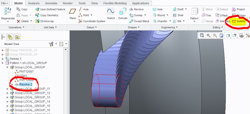
In this case some of these fails.
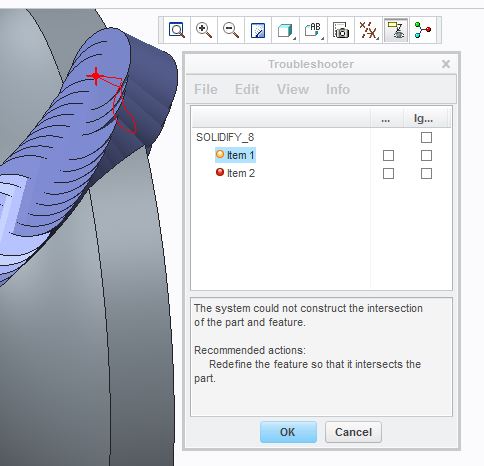
It is what you talked before?
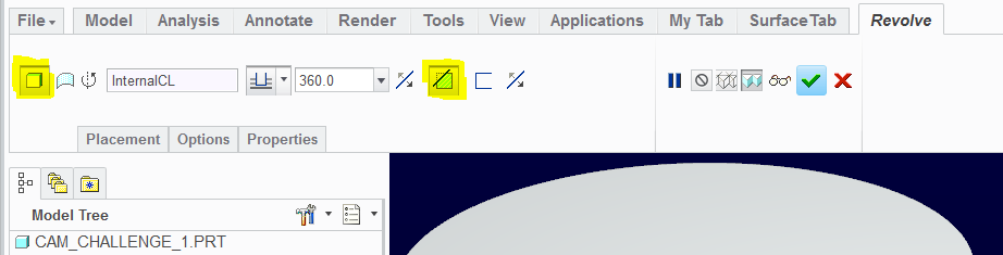
Just edit definition on the 1st instance of the revolve. Change it to "solid cut". All the patterned instances will follow.
hello brother Giulio Fraulini how you take a trace curve....can u upload ur creo file where u make a trace curve,,,,i am facing problem regarding same thing...i want to make globoidal cam....but dont know how to model it,,,,can u please help me rrrregarding it.. please check image..this is what i want to make,,...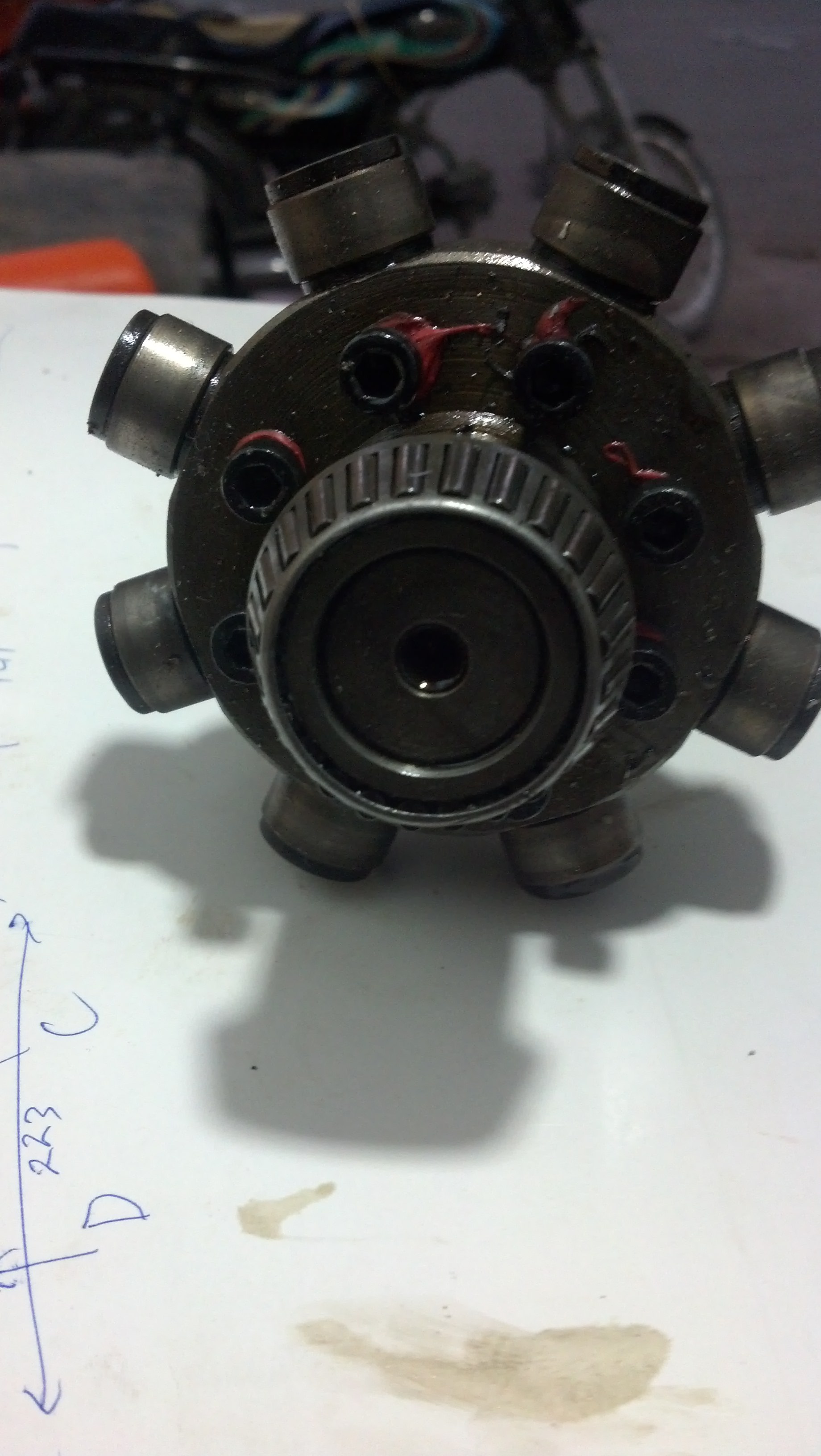
thanks
asif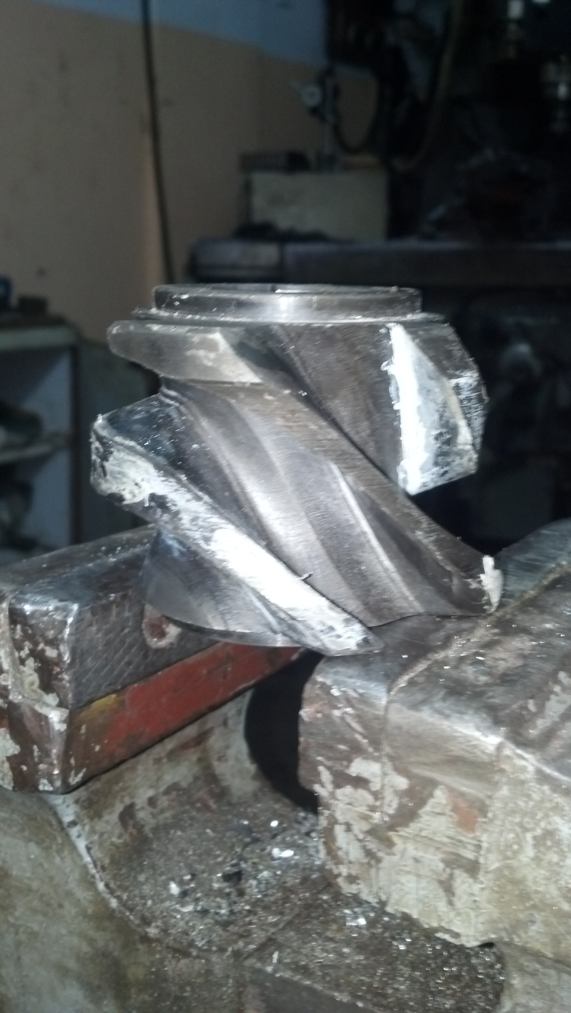
These are great mechanisms. Thanks for posting the images.
If you know how to make trace curves, the trick is making the second motion object the "paper" (selection in the top of the trace curve dialog), and setting the output to 3D. Therefore, I pick a point on the roller bearing and I select the cam as the paper space. That will create the curve in the cam component.
Remember that you need the motion and the analysis complete so you can select it as the basis of the curve.
If you still cannot get it, I will upload the files later today as I am heading out the door right now.
This is the video of how the 3D trace curve was generated.
![]()
Hi all,
Antonius has preceded me with the post of a video.
I found the manner to better draw this cam and I want to make a video tutorial.
Unfortunately, in this days I had not much free time, furthermore I'm not practical with software for screen video.
Just I'll be ready, I'll post what I've done with some references.
Dear Antonius Dirriwachter...
thanks for this video.....and ur time....but if u see my model file...i am confouse that how much servo motor i have to attach with this assemble.....and how i control the motor to match the orignal working condition of this cam mechanism....i only just know that this is 8 ststion type dividing mechanism with some delay time during the neutral are of cam..i realy want to match the original working condition with my model...and after that i am able to make a trace curve for further modeling.....pleaseeee...if u still not check my file..please check it for better understanding of ervery person problem who want to make this type of camm...
regards
asif
respected Giulio fraulini..thanks for ur concern over my problem...i waiting ur tutorial....and also which software u r practical with???
regards
asif
http://communities.ptc.com/videos/5576
Remaining in PTC ambit, I am practical with MathCad 15 and Creo 2; but I don't understand this what has to do with the main argument.
Regards
Thank you for the video, Giulio.
I have a question regarding the cylindrical cutting too. How are you accounting for the difference?
Maybe I missed it in the video, but I am trying to understand alternatives to pattering the cutting tool.
Asif, generating the desired motion profile is a separate discussion.
There are several ways this can be done based on a simple x-y graph of the desired profile.
Profiles that use sinusoidal profiles are easier to program.
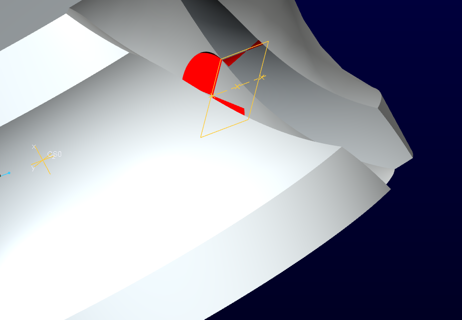
I suspect there is a problem with your measurement analysis for clearance. If you are checking clearance in the same locations as the trace curve, then yes, you will have zero clearance. If you check clearance globally (collision), you will see this before and after the current position. This is what I was trying to show you in the 3rd post.
Along the radial position, this is not an issue. Only along the z-movement (helical movement) of the rollers is where this becomes prevalent. This is easy to check. In the groove, Create an axis between the 1st two trace curves at ratio 0.5. create a plane and revolve cut of what would be your roller bearing profile (including depth). You will find that there is material being cut with this operation, before and after the position of the measurement done with the analysis.
I only say this because in practice, if the part is being machined using a cutter the same diameter as the bearing (with clearance of course), this anomaly would be averted due to the motion of the mill and lathe. But if the is done with a cutter that is smaller with a number of passes, and you are concerned with minimal and consistent clearances, you will have to account for this. If the parts will be processed using a rapid prototype method where conventional tooling is not used, your cam will bind.
Generally, the sweep method and the boundary blends will generate the same profiles. You actually only need two trace curves for the sweep. You can compensate for the issue I raise with making the cut deeper (obviously) and wider to make sure that cut with the patterned cuts is fully cleared. If you want to make sure that your model is 100% accurate, and you want to manage a minimal clearance along the entire path, you have a lot more work to do. With a sweep profile, you can make a variable sweep that follows additional curves. created from known points along the path. These are the points where the patterned revolve cuts removed material.
-Most- of us do not need to be concerned with this as learned craftsman already know about this phenomena. But if you have to analyze a failure or some unexpected anomaly when you build your parts, maybe this discussion will give you some insight as to what might have happened.
Asif, this may help a little in defining motion with custom servo motion rather than tables...
Radial Ball Bearing: Checking your mechanism links
and some more here... see the WF 2 link in comments...
Motor Profiles - study tools and observations
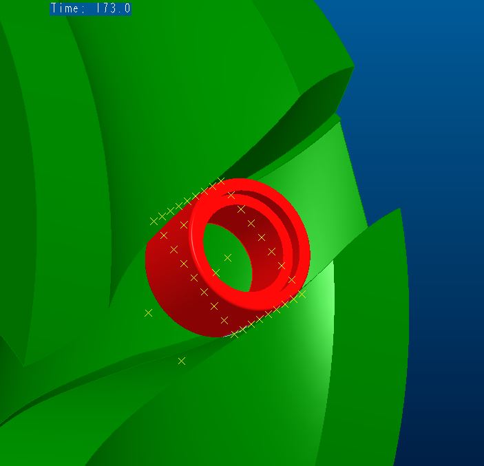
For anyone interested, I attached a Creo 2.0 version of the video file. Just run the mechanism analysis to get the motion and play with the motion profiles and such. The drive servo motor is the default 10 second ramp and the driven motor is user defined for the 8 seconds of dwell and 2 seconds of motion (cosine*180).
I simplified the sweep by using thicken with center offset from a surface ribbon following 3 trace curves.
I did not do a lot with the interference issue here other than to provide some feature to either minimize it or just have a default clearance to account for it. Again, if you tell a machine shop the motion you need, they know what to do with that.
The idea of this part is that if you were to 3D print it, it would function.
![]()
I check clearance between parts, and not in the same locations as the trace curve.
In "partial collision detection" check in playback tab, inside mechanism environment, nothing enter into collision.
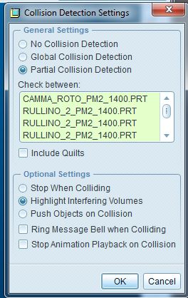
I attached a pdf file that explains the question.
Also the measure feature checks that there aren't compenetration (as I showed in the video into the ppt file). Naturally, you have to stare that inside mechanism, where it does the verification over all the time.
Interesting, it's like a 90deg version of a Geneva drive.....
https://www.youtube.com/watch?v=HQr4P5WMA-w
Unfortunately, we cannot do solid-body sweeps. That is ONE big area where Solidworks actually has an advantage. This capability is LONG overdue. PTC, are you listening????
Interesting. I will have to review this. I am finding all kinds of deviations depending on the method used.
Thanks for posting.
We do have motion envelopes which is what SW does. They seems to still be very crude. It also doesn't use the "paper part" method of trace curves. If the two were united, then you might have something.
Overall, this is indeed an interesting subject. I overlayed a swept solid to a thickened solid and ended up with wildly different shapes. One of the major issues here is one that is compounded by the significant difference between the normals of the inside and outside curves. Sweeps can only utilize one. With the reversal, other sweep methods have to be broken up or it will fail. It is yet another mobius problem.
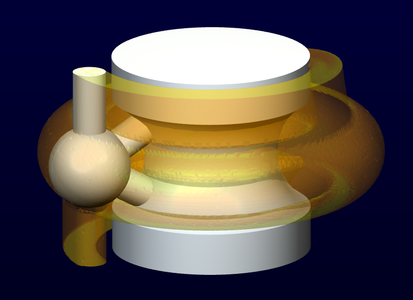
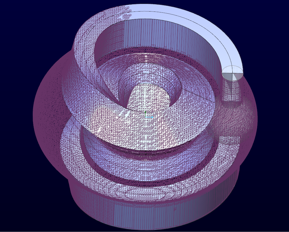
This is the motion envelope for the cam. 112,000 polygons and nearly 30Mb.
Enough to bring my computer to its knees.
In order to get the motion, you have to plan on being able to move the entire mechanism.
And talk about mobius,,,

I suddenly have a hankerin' for a softserve 
Oh man, nice!
I actually had some thoughts on that this weekend. When I get some time I'm going to play with it. Reminds me of playing with AotuCAD in the early/mid '90's and patterning boolean cuts like that. Ouch.....
Here it is my files.
I hope that they could explain well what I've done.
With the envelope generation, I can create a very close surface on the inner and outer faces. The problem is the face that counts; where the bearing rolls. It is an involute face.
I will have a look at your file to see what may be resolving inherent issues. It is sort of amazing that it requires a study to solve what is actually simple in real life. But with rapid prototyping on the rise, our software should be able to "easily" recreate real world machining operations.
Below is what I know is accurate, but "facetted". And with Creo 2 M040, patterns are still buggy.
This has been my long time solution to such problems.
Giulio, thanks for being so persistent with me and providing this file.
I confirmed your findings against the known validation model above.
Indeed, the surface offset method for the walls where the rollers ride creates an accurate roller surface.
The initial sweep based on the two trace curves are all that were required. This appears the only valid sweep as all others seem to deviate due to a twisting action in the trajectory.
I used the offset on the file above and it came out identical (within the graphic limits, obviously).
I then went back to the envelope model I was working with for validation. The offset surfaces from a center sweep did much better than all the sweeps and blends I was able to throw at it.
I also compared the offset to the thicken and when it does not fail, they are also identical. This means that asm0066 above should also be correct (I will review again).
The only difference I found with the envelope model was the bottom of the milling operation. The boundary blend is an approximation. This is no big deal as this is not a functional feature. Just be aware that if milled, it will be somewhat different. I conformed this with a revolve of the mill in the bottom of your cam.
This is the overlay. Very good conformance on the cam surfaces. I could not achieve this with sweeps or boundary blends.
.
Boundary blend approximation of actual bottom milled surface...
This is the difference with the shaded envelope...
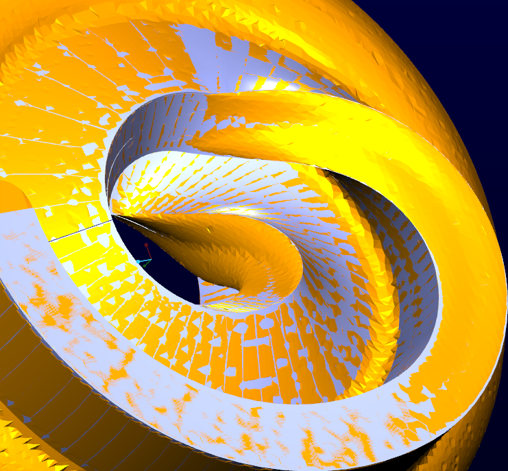
This is the mill shape in the bottom of your cam..
What is nice is that this image shows the tangency between the mill bit cylinder and the offset walls.
I will see if I can make a motion envelope of you device.
Great work, Giulio! Thank you again for sharing.
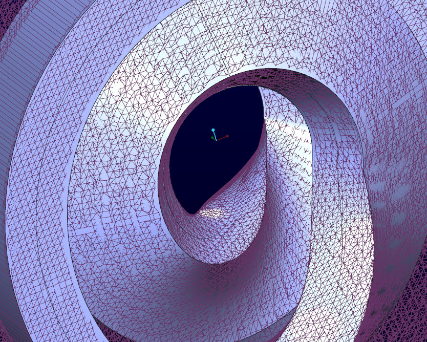
I reworked your file to get the rollers to generate an envelope. Since I cannot work with skeletons, and since PTC found it "useful" to lock the 1st placed components locked to "default"... I had to replace the skeleton part with a pin-constrained reference part. Fortunately, all the motion features were preserved. I did not have to redefine any of the motors. I simple applied a gear connection to my replacement "skeleton" and the action was "reversed".
The envelope model was generated at the max resolution of "10".

Wow, your PC must HATE you for this one! 
It is actually not too bad on the CPU. But I did run into a bug in the selection process.
There doesn't seem to be any way to tighten up the coarseness.
Nice thing is that selecting two opposite ends on this mechanism will create a closed loop.
By making it an assembly with 3 envelopes, it removed some of the artifacts.

Giulio; I found GRAPH_1 in your assembly model. What was that used for?
I've tried to make the 3D curves guided by the graph, as I saw in some documents.
But in that manner, you should have the graph that was accurate, and with graph tool you can only SKETCH the graph curve...it is not properly accurate...Or may I don't know how to use that tool.
In the files I've uploaded was remained the graph feature.
That is what I was thinking.
True, there are some useful tips for making good graphs and some tips on how to use splines with better accuracy. I will explain more later today.
Hello Giulio fraulini....really impressive work...please can u tell me how to make a table for servo motor.for run at certain time and rotation...
Regards
Adif
Hi,
I've made it with an internal software we have at work.
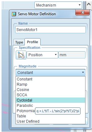
The type of the law is a sinusoid, like the type you can find in proE
In other way, I write the law in MathCad, and I export it as points' curve into a text file.
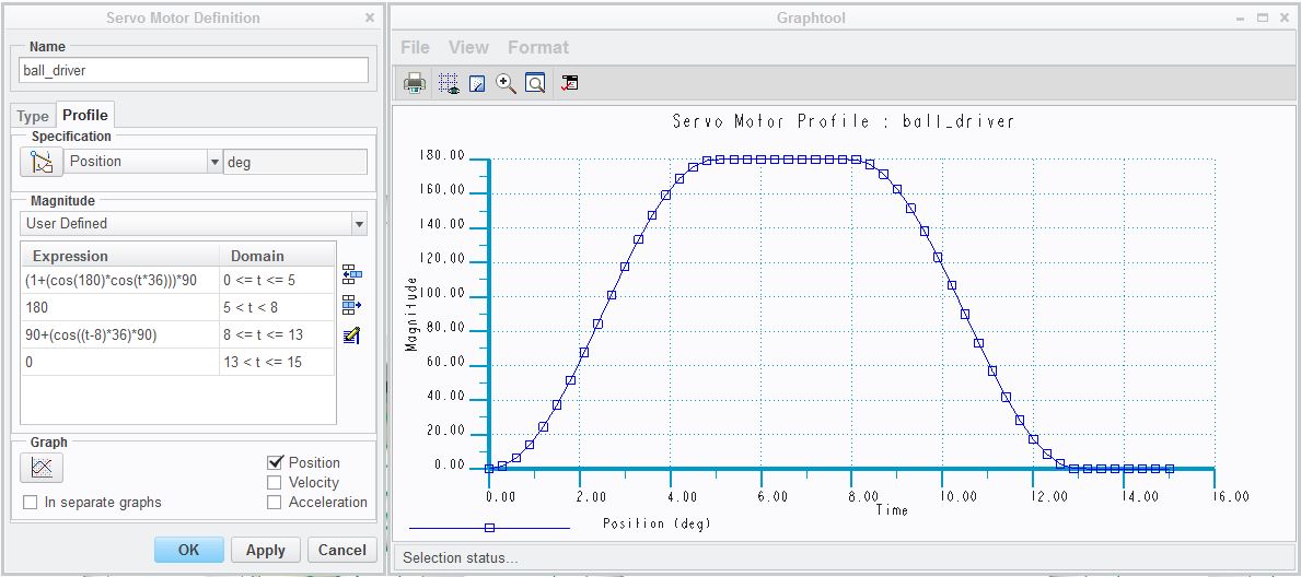
Here is a very straight forward sinusoidal sweep with defined dwell times for a servo motor.
the math gets a little tedious as you have to keep track of "t" within the process, but it is fairly easy to edit and watch the updated graph. If the sequence suddenly changes, it will warn you and show you the results.
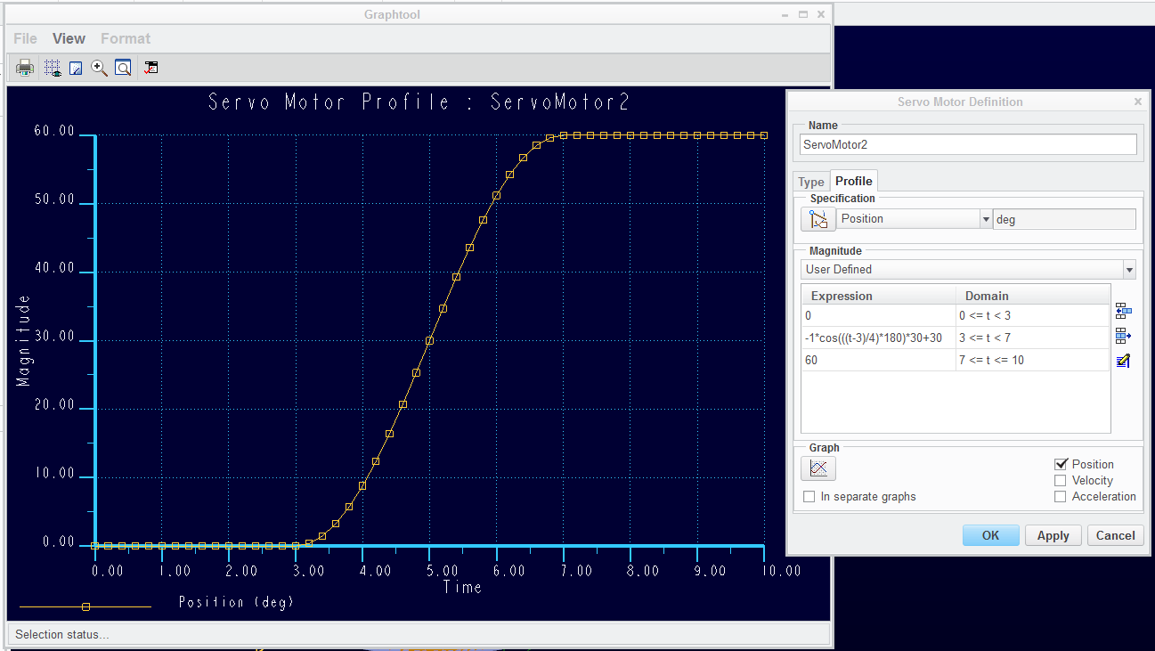
This one dwells for 3 seconds at 0 degrees; "-1*" inverses the cosine; "(t-3)" resets t to 0; "/4" account for 4 seconds for a 1/2 cosine sweep making t range 0 to 1; "*180" makes the sweep 1/2 cycle; *30 set amplitude (1/2 of overall since the cosine function returns -1 to 1); the "+30" manages the offset to start at the last known position... in this case, 0. Followed by another 3 seconds of dwell, holding at position at 60 degrees. In angle terms... you could divide the time segment into 360 steps and you time would equal 1 degree per value of "t".
Be sure the domains remain continuous.
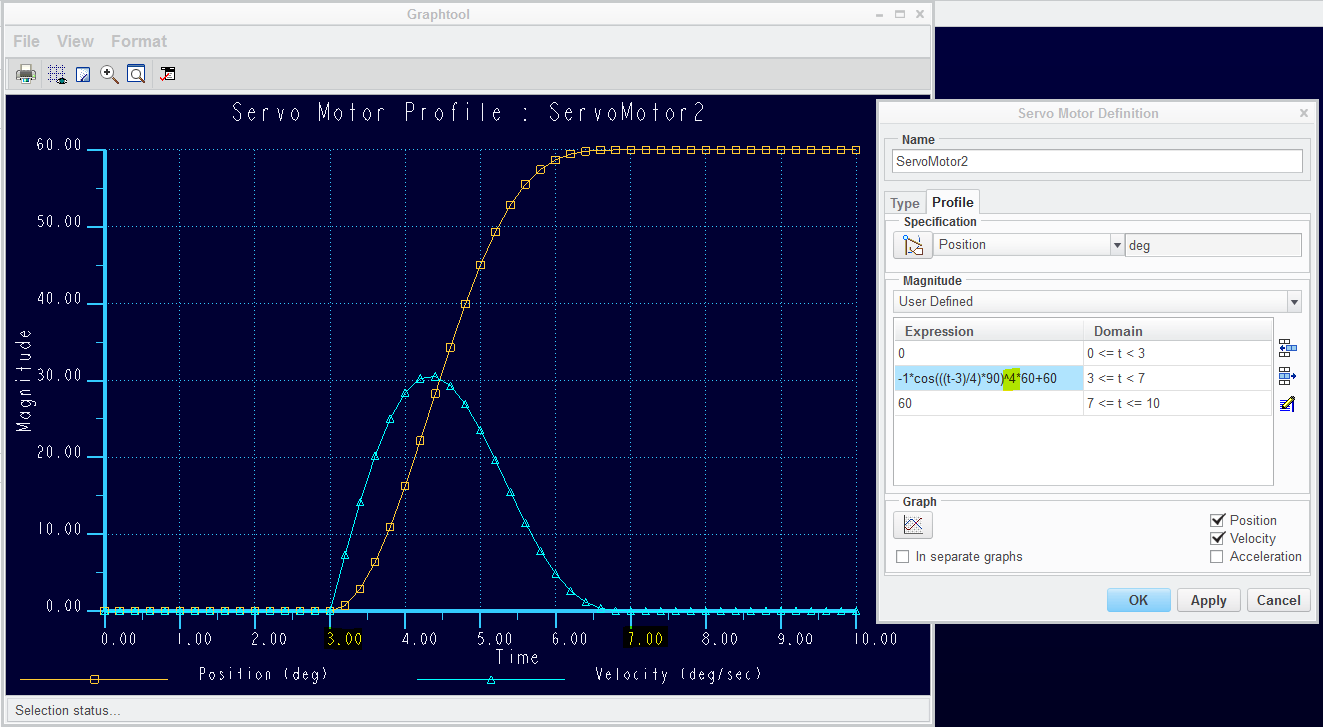
...and as an aside, you can change the curve somewhat using power functions on the Cos statement.
Here you have a hard start and a soft stop by brining the statement up to the power of 4. You can play with both sin offsets and cosine to tweak the profile you prefer. I don't know why you'd do that, but it can be done.
Giulio, the process of making graphs with an arithmatic equation is not too difficult but certainly not direct. You can project an equation curve into a sketch. You can save the sketch as a .sec file. You can then insert (get data) the section file into the graph.
Here is a comparison; top is the graph driven sweep, and the bottom is a cosine equation datum curve.
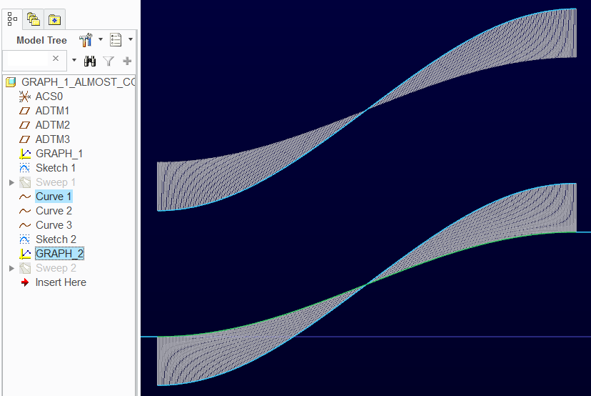
Attached is the source section file.
Another way to get a points file is to pattern points along an equation datum curve. When you export this, you can easily extract the point locations to manipulate in excel or elsewhere and bring it back into the mechanism table driven servo. Be careful with this, however, since the time steps for patterning is not always as accurate as you would want. this is why I prefer writing the equation in the servo definition itself.
As for splines... yikes! Yes, they need help in the user interface. One issue is locating that intermediate point. You cannot move it once it is placed. This means that the ratio along the spline is fixed. And it affects every other action form then on. If you are "certain" the midpoint is exactly 50% along the curve at creation, it will stay there and you can work with it. But if it is arbitrary, all hope is lost. However, you can control radius of curvature and tangent angle directly from the spline... or you can use the controlled polygon mode. Either way, you want to know exactly where any of the points between the ends are located with respect to ratio along the curve. There is one way to manage the points along the curve using a local coordinate system. But even that has implications. It is not as simple as saying, for instance, "1/2 way along the curve".
I didn't know graphs did this during playback
(the red tracking line in from the measure graph)
![]()
oh, and yes, you can make point files from these graphs too.
No matter how often I do it, I can never get use to capturing graph data into a file that can be imported as a curve.
However, each time I do it, I seem to learn something new.
I defined a motor profile using a cosine function.
The preview graph only used 0.2 second intervals. I couldn't find a way to change that.
However, when I define the analysis, I could set the step size. In my test case it was set to 0.1 seconds.
I can then use the mechanism Measure to get the axis rotation based on the analysis and it returns ever step of the analysis.
I can save that measure graph to a text file.
I edit the text file to replace the header (1st 4 lines)
Open Arclength
Begin section
Begin curve
...and rename the .txt to .ibl
Next, you can read the .ibl file to a "Curve from File" ...which for some extra-ordinarily silly reason, is not in the ribbon. When you use the command search just type curve and it shows up.
Select a coordinate system and then select you .ibl file.
The thing I learned today is that the .ibl file does not need a Z value! This is huge as you do not need to do this in Excel.
Now you can make the section by projecting the curve into the section...
Then you can save the section...
Then you can import the section into the graph... and add the coordinate system it wants... and lock the remaining applicable dimensions. Be careful not to let the imported section get distorted.
See, simple !!! 
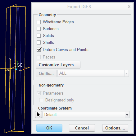
...and importing iges files into datum graphs works too. This eliminates the interim section generation.
Ugh... this actually kills me. I'm in the Creo NC Enhancement meeting right now and I am still struggling to completely understand this issue. I'm trying to get trained up enough right now so I can communicate this to the team.
'Sup Brian! Hope all's well with ya! We're looking forward to being able to use solid bodies to add or remove material in sweeps etc.. I've run into this before as well, and had to fudge things. Good luck!
Have a look at these videos... it is a pretty simple thing to wrap your head around...
And this thread...
Hope that helps...
...need to find the video to show that SolidWorks does this already 
Funny how advanced Pro/E is......yet for this you still have to use almost the exact same technique I had to use in the early '90's as a boolean operation in AutoCAD to do a barrel cam.....
How did it go with the meeting?
Did you discuss this argument with your colleagues?
Regards
hello i asif here....really want to thanks all participant of this thread(specially Giulio Fraulini and Antonius Dirriwachter..because with the help of there inputs and illustreated help and uploaded files//.. i am able to make my globoidal cam ...model....please look this video ...and give me suggessition regarding manufacturing .....
Pretty cool!
Maybe some of the Creo manufacturing extension guys can help with this.
It is worth a separate post on how to best prepare for the machinist.
Basically, the machinist needs to duplicate the motion of the rollers while rotating the cam.
Yeah, the machinists need the two motions I have gave to the two motion axis: the cam and the follower.
1)The cutter, that should be the roller in my assembly, has to rotate of an arc with the motion law that I've give to the follower, while, obviously, the cutter rotates on its own axe;
2) the cam has to rotate with a constant velocity;
3) the two motions must be synchronized.
Heh, if all this was done to get the cam manufactured, then you have really given yourself a hard time. The manufacurer doesn't need a 3D model for a cam like this. All you need is the moving profile of the follower versus the rotation angle of the cam. And specify some tolerances.
To our manufacturers we give the drawing and the points file of the motion axes.
True, if you're using a 3rd party cam manufacturer that has specialized cam software. If however you want to produce it yourself internally without specialized cam software, you're going to need an accurate 3D model.
....but what FUN would that be?
That's why I didn't say anything till now 
I'm very impressed with all the modelling in this thread, wouldn't want to have missed it!
I am not sure I want the CNC programmer to follow the edges, but rather go back to the intent.
Since the rotating mill head will be offset in Z anyway, it requires interpolation. A circular path for the center of the roller shaft is one point on the mill axis so it is easy to accomplish and easily interpolated into angles. The path for each step anywhere inside that radius is the mill head angle. The trace curves is created on a series of points that seem to be double precision. There are 600 points generated. I don't know if this is a constant but this was for 3 revolutions. A spline is driven through these points which never has sharp corners. Therefore a curve is fitted to points but makes up its own mind between points. Of course, those points are not on an evenly spaced angle measurement, they are based on distance to the next point.
I would want to work with a programmer that can input the curve as given by a sinusoidal law if that is the motion of the cam, or some other arithmetic representation. So far, I've had pretty good luck defining the cam that very same way. This minimizes any rounding or offsets that might exist in point interpretations or some other projection technique.
Speaking of offsets, a good code person for CNC will also know how to interpolate for using smaller mill cutters. Since this discussion has assured that a surface offset functions properly, an axis offset too should be equivalent. This is much better than trying to use a mill cutter at the exact diameter of the roller with clearance. This will also lessen the deformation in the floor of the cut. I am not certain at this point what else may change in the mill axis by doing this. Again, this is where the CNC people get paid the big bucks. This is also why you would want to be able to confirm the work and know it is correct within the CAD software. If you question the skills of the programmer, definitely confirm the characteristics using a smaller mill cutter. If this discussion has taught us anything it is to really confirm the reliability of your data, and assumptions.
The key takeaway from parts like these is that they are subjected to very high loads. The rollers must have linear contact after a short break-in period. If the machining is done wrong, the life of the parts are highly compromised. In this case I certainly agree that the CAD model should be as close to accurate as possible. You should be able to do a 3D inspection scan and overlay the cad model, and they should be very close to the same within the allowable tolerance if not identical.
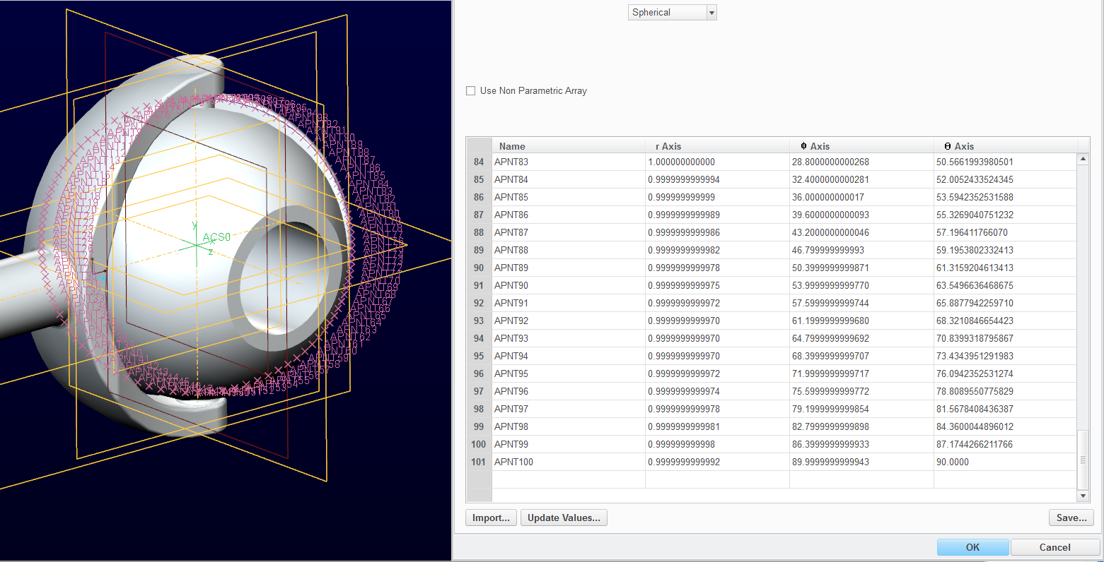
A little more information. 1st of all, you can get all kinds of point files including cylindrical and spherical output. However, I question the accuracy level. I have the accuracy set to default (relative .0012) and this is the return of the trace curve set to spherical. I get 100 points and the trace point is exactly 1" away from the CSYS. That means that R should always be 1.00000000000. Judge for yourself if this level of accuracy matters to you. Changing the accuracy to absolute at .00005 did -not- change these values! I don't know if this error level is the result of the trace curve or the precision used for the analysis. I suspect the ladder. 100 points for a 360 degree element seems a little sparse to me.
Hmmm, that's interesting. I remember back in the day when they "fixed" pi. I used to be if you used it in an equation, it was always a little off (as on wraps - then formed datum curves), then they fixed it. Maybe they need to go over this as well?
Numbers are all -off- a little in Creo Parametric. Anything beyond single precision seems to be fair game.
Too many number return x.9999999999 when you look at the actual property value regardless of how accurately you input the value.
This is also maddening when you input equations into pattern values for instance. It defaults to whatever your number of digits is set to and locks to that truncated value. You have to go back and enter a relation for those values that will properly evaluate the pattern. Values of 1/3 or 2/3 come up all too often as a real requirement, but it takes two steps to actually do that. If you don't know about it, you end up chasing your tail trying to solve this significant error level.
Yup!
이 문서는 다음 토론에서 생성되었습니다. Modeling a globoidal cam
This thread is inactive and closed by the PTC Community Management Team. If you would like to provide a reply and re-open this thread, please notify the moderator and reference the thread. You may also use "Start a topic" button to ask a new question. Please be sure to include what version of the PTC product you are using so another community member knowledgeable about your version may be able to assist.
Labels:
- Labels:
-
General
1 REPLY 1
Jul 12, 2016
08:10 AM
- Mark as New
- Bookmark
- Subscribe
- Mute
- Subscribe to RSS Feed
- Permalink
- Notify Moderator
Jul 12, 2016
08:10 AM
Hee-Beom Lee, why have you copied the contents of an existing discussion (Re: Modeling a globoidal cam) into a new document? What are we gaining by duplicating the information?
Announcements
Top Tags
