
Turn on suggestions
Auto-suggest helps you quickly narrow down your search results by suggesting possible matches as you type.
Showing results for
Turn on suggestions
Auto-suggest helps you quickly narrow down your search results by suggesting possible matches as you type.
Showing results for
Community Tip - Want the oppurtunity to discuss enhancements to PTC products? Join a working group! X
Options
- Subscribe to RSS Feed
- Mark Topic as New
- Mark Topic as Read
- Float this Topic for Current User
- Bookmark
- Subscribe
- Mute
- Printer Friendly Page
Plot shear force and moments in Mathcad
Nov 16, 2015
10:59 PM
- Mark as New
- Bookmark
- Subscribe
- Mute
- Subscribe to RSS Feed
- Permalink
- Notify Moderator
Nov 16, 2015
10:59 PM
Plot shear force and moments in Mathcad
Hello all,
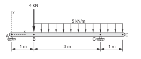
We are learning shear force and moments and we are drawing them by hand. I understand all the calculations and how to draw shear force and bending moment diagrams but the bonus question on our assignment is to plot the diagram below in Mathcad using x-y graphs. If someone could help me with it I would really appreciate it. We Wont be taught how to do it in Mathcad but i am sure it would be useful to know.
Solved! Go to Solution.
Labels:
- Labels:
-
Algebra_Geometry
1 ACCEPTED SOLUTION
Accepted Solutions
Nov 18, 2015
02:52 PM
- Mark as New
- Bookmark
- Subscribe
- Mute
- Subscribe to RSS Feed
- Permalink
- Notify Moderator
Nov 18, 2015
02:52 PM
Now that you have solved the problem, attached is my take on it. Certainly not the only way.
A few things to note:
1.) Instead of defining functions with numerical values (either given or calculated), I assign a variable to each piece of information and then use the variable in the function definitions. This is crucial in “real-world” use of Mathcad for adjustability & reusability. Image you’re working on a project where the initial design is as shown in your problem, but then the 1m cantilever is later changed to 1.5m. In your document, you’ll need to go through and make the adjustment in each equation. In my document, you just change one variable.
2.) I used “option 2” to define M(x). See if it makes sense to you. As an added bonus, I showed (on sheets 4-5) how to back-calculate the moment equations for each segment.
3.) Add descriptive text. I was lazy and did not do this in the attached document. However, text is very important to give the reader an explanation of what the equations show.
44 REPLIES 44
Nov 17, 2015
07:52 AM
- Mark as New
- Bookmark
- Subscribe
- Mute
- Subscribe to RSS Feed
- Permalink
- Notify Moderator
Nov 17, 2015
07:52 AM
I would suggest that you provide your workings to save collabs having to search for the correct formulae.
Mike
Nov 17, 2015
09:38 AM
- Mark as New
- Bookmark
- Subscribe
- Mute
- Subscribe to RSS Feed
- Permalink
- Notify Moderator
Nov 17, 2015
09:38 AM
Not your problem, but an example of how you can do it
Nov 17, 2015
08:00 AM
- Mark as New
- Bookmark
- Subscribe
- Mute
- Subscribe to RSS Feed
- Permalink
- Notify Moderator
Nov 17, 2015
08:00 AM
1st step: solve for your reactions at A & C in Mathcad and post your file (if working in one of the Prime versions of Mathcad, it's also good to post a screenshot). I'll give you the 2nd step once you complete the 1st.
Nov 17, 2015
08:20 AM
- Mark as New
- Bookmark
- Subscribe
- Mute
- Subscribe to RSS Feed
- Permalink
- Notify Moderator
Nov 17, 2015
08:20 AM
Matt Hastie wrote:
Hello all,
We are learning shear force and moments and we are drawing them by hand. I understand all the calculations and how to draw shear force and bending moment diagrams but the bonus question on our assignment is to plot the diagram below in Mathcad using x-y graphs. If someone could help me with it I would really appreciate it. We Wont be taught how to do it in Mathcad but i am sure it would be useful to know.

If you have to draw that particular diagram using Mathcad x-y graphs, that's more than just a bonus question. It involves, creating expressions/functions to describe the bar, the arrow heads, the numbers, the letters and the support shadings. It can be done, but it's not simple. See this link for very good library of routines to draw such things: Creating Amazing Images with Mathcad 14
And have a look at Hatch or Shading of a Region of a Plane
Stuart
Nov 17, 2015
08:46 AM
- Mark as New
- Bookmark
- Subscribe
- Mute
- Subscribe to RSS Feed
- Permalink
- Notify Moderator
Nov 17, 2015
08:46 AM
I believe he meant that he has to plot the shear & moment diagrams (example) for that particular case.
Nov 17, 2015
09:46 AM
- Mark as New
- Bookmark
- Subscribe
- Mute
- Subscribe to RSS Feed
- Permalink
- Notify Moderator
Nov 17, 2015
09:46 AM
Mark Gase wrote:
I believe he meant that he has to plot the shear & moment diagrams (example) for that particular case.
OK. That's simple enough. I misread the question, and thought that his saying he knew how to draw shear and moment diagrams meant he knew how to draw those in Mathcad, but didn't know how to draw a diagram that showed the force loadings at each point (again, if it's just a "stick man" diagram, not too difficult but an annotated diagram needs a little bit more work)
Stuart
Nov 17, 2015
01:47 PM
- Mark as New
- Bookmark
- Subscribe
- Mute
- Subscribe to RSS Feed
- Permalink
- Notify Moderator
Nov 17, 2015
01:47 PM
If you have to draw that particular diagram using Mathcad x-y graphs, that's more than just a bonus question.
That depends on the size of the bonus 
Nov 17, 2015
10:42 AM
- Mark as New
- Bookmark
- Subscribe
- Mute
- Subscribe to RSS Feed
- Permalink
- Notify Moderator
Nov 17, 2015
10:42 AM
I have solved for the reactions at A and C. This is as far as we have gone.

Nov 17, 2015
11:42 AM
- Mark as New
- Bookmark
- Subscribe
- Mute
- Subscribe to RSS Feed
- Permalink
- Notify Moderator
Nov 17, 2015
11:42 AM
Matt, good work so far.
The next step is to create a function that defines the shear force given "x", i.e. define V(x). You may find it easiest to create three separate functions: one for shear between A & B, one between B & C, and one between C & D. Remember, however, that the origin of x is always at A for all three equations. Then there are a few ways to combine them into one function.
Nov 17, 2015
01:09 PM
- Mark as New
- Bookmark
- Subscribe
- Mute
- Subscribe to RSS Feed
- Permalink
- Notify Moderator
Nov 17, 2015
01:09 PM
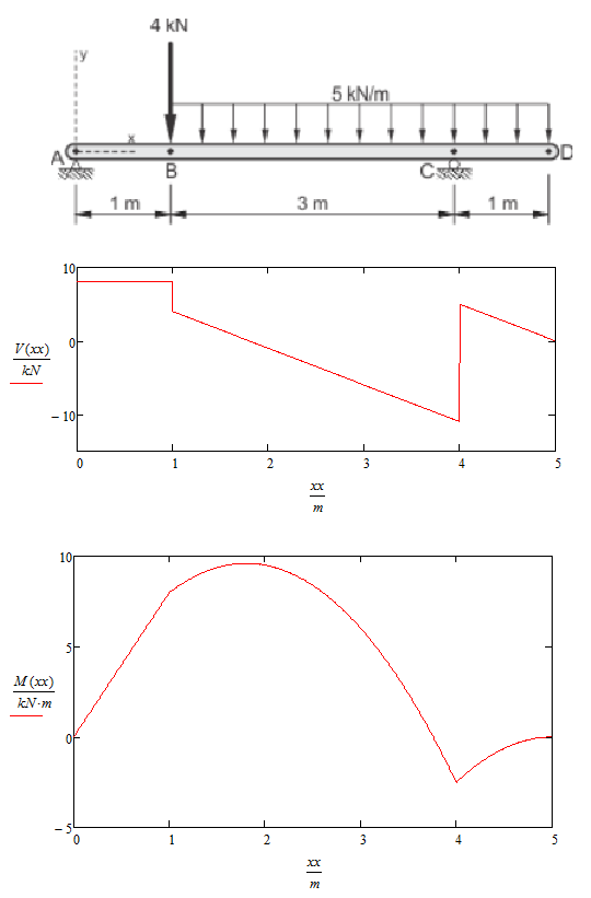
As a teaser, here's what I get:
Nov 17, 2015
01:15 PM
- Mark as New
- Bookmark
- Subscribe
- Mute
- Subscribe to RSS Feed
- Permalink
- Notify Moderator
Nov 17, 2015
01:15 PM
I'm not sure what you mean by creating shear functions between each point. should I do what I did for the force calculation but find x between each point.
Nov 17, 2015
01:23 PM
- Mark as New
- Bookmark
- Subscribe
- Mute
- Subscribe to RSS Feed
- Permalink
- Notify Moderator
Nov 17, 2015
01:23 PM
Your first post said, "I understand all the calculations and how to draw shear force and bending moment diagrams. . ."
So how do you get the shear at (for example) 2.5 meters from A? (You have to have an equation for shear at any point along the beam--that's "shear as a function of x.")
And how did you graph (by hand) the moment along the beam? (You had an equation--moment as a function of x.)
You need to write those equations in Mathcad, then insert a 2D plot that displays them.
Nov 17, 2015
01:24 PM
- Mark as New
- Bookmark
- Subscribe
- Mute
- Subscribe to RSS Feed
- Permalink
- Notify Moderator
Nov 17, 2015
01:24 PM
What is the equation of the shear diagram between A & B?
V(x):= ?
for 0m < x < 1m
Nov 17, 2015
02:03 PM
- Mark as New
- Bookmark
- Subscribe
- Mute
- Subscribe to RSS Feed
- Permalink
- Notify Moderator
Nov 17, 2015
02:03 PM
Section A-B Vx=8kN between B-C Vx=9-5x and C-d Vx=-6-5x. Im hoping my math is right.
Nov 17, 2015
02:14 PM
- Mark as New
- Bookmark
- Subscribe
- Mute
- Subscribe to RSS Feed
- Permalink
- Notify Moderator
Nov 17, 2015
02:14 PM
AB - good, now put it in Mathcad (including units)
BC - good, now put it in Mathcad (including units)
CD - try again. Keep in mind what the endpoints (x=4 & x=5) should be. When evaluating V(4m) for section CD, remember that you want the shear just to the right of point C (i.e. include the effects of the reaction at C).
Nov 17, 2015
02:00 PM
- Mark as New
- Bookmark
- Subscribe
- Mute
- Subscribe to RSS Feed
- Permalink
- Notify Moderator
Nov 17, 2015
02:00 PM
When you solved this problem by hand, I realize that you probably did not explicitly determine the equation of the line you drew. I assume that you were taught (as I was) to calculate the shear as specific points. Using those points and a certain understanding of the underlying physics, you drew straight or curved lines connecting those points. For the straight lines, your algebra & geometry skills should allow you to determine the equation of a line that intersects the two points.
Tell/show us what you know, and we'll help you out.
Nov 17, 2015
03:20 PM
- Mark as New
- Bookmark
- Subscribe
- Mute
- Subscribe to RSS Feed
- Permalink
- Notify Moderator
Nov 17, 2015
03:20 PM
Your right Mark. We do not have to determine the equations for our line. We are just drawing out the diagrams. We have limited knowledge of Mathcad. Up to this point what you are asking me to do in Mathcad is beyond what we have learned so please bare with me. Here is what I have but I cannot get it to compute. 
Nov 17, 2015
03:38 PM
- Mark as New
- Bookmark
- Subscribe
- Mute
- Subscribe to RSS Feed
- Permalink
- Notify Moderator
Nov 17, 2015
03:38 PM
No problem, Matt. Your use of a solve block to find the reactions at A & C lead me to believe you had a better understanding of Mathcad - it's a more advanced feature than I would expect a beginner to know. You just keep trying (like you have been), and I've got no problem bearing with you.
My suggestion would be to define three functions. There is no need to include a solve block (given... find) for these functions. The first could be:

See if you can define the other two.
Nov 17, 2015
04:45 PM
- Mark as New
- Bookmark
- Subscribe
- Mute
- Subscribe to RSS Feed
- Permalink
- Notify Moderator
Nov 17, 2015
04:45 PM
Is this correct?
Nov 18, 2015
07:41 AM
- Mark as New
- Bookmark
- Subscribe
- Mute
- Subscribe to RSS Feed
- Permalink
- Notify Moderator
Nov 18, 2015
08:14 AM
- Mark as New
- Bookmark
- Subscribe
- Mute
- Subscribe to RSS Feed
- Permalink
- Notify Moderator
Nov 18, 2015
08:14 AM
Looks good to me.
As shown by Fred, you can define x values for each segment and plot your shear diagram that way. However, I think he was just showing you this as a way to check your own work. For a better presentation, I would recommend that you now define a single function, V(x), that uses one of the three functions you just wrote depending on the value of x. Any thoughts on how you could achieve this? I can help you with the implementation in Mathcad, but based on your knowledge of other math and/or programming software (e.g. Excel), try to explain in words what the approach should be.
Nov 18, 2015
08:56 AM
- Mark as New
- Bookmark
- Subscribe
- Mute
- Subscribe to RSS Feed
- Permalink
- Notify Moderator
Nov 18, 2015
08:56 AM
All I can think of would be using an if,or,else statement. Am I on the right track. Other than that I have no idea.
Nov 18, 2015
09:01 AM
- Mark as New
- Bookmark
- Subscribe
- Mute
- Subscribe to RSS Feed
- Permalink
- Notify Moderator
Nov 18, 2015
09:01 AM
An if statement program would work. Don't forget that Mathcad also has Boolean operators, so if x := 3 the expression (x>2) will evaluate to 1 (and can be used as a multiplier) and the expression (x<2) will evaluate to 0. These can be used to turn function "on" and "off" over specific ranges.
Nov 18, 2015
09:07 AM
- Mark as New
- Bookmark
- Subscribe
- Mute
- Subscribe to RSS Feed
- Permalink
- Notify Moderator
Nov 18, 2015
09:07 AM
Yes! There is more than one way, but this would be my go-to approach.
Mathcad has an "if" function. However, for a case like this I would recommend using the programming "if" operator. Take a look in the help menu under "Programming" -> "Conditional Operators". Or, I'm sure there are examples of its use on this forum. See what you can come up with on your own.
Nov 18, 2015
09:11 AM
- Mark as New
- Bookmark
- Subscribe
- Mute
- Subscribe to RSS Feed
- Permalink
- Notify Moderator
Nov 18, 2015
09:11 AM
Remember that "programming" is not available in Express. Using full Prime would be okay, but those poor souls restricted to the "free" Express version would be out of luck.
Nov 18, 2015
09:31 AM
- Mark as New
- Bookmark
- Subscribe
- Mute
- Subscribe to RSS Feed
- Permalink
- Notify Moderator
Nov 18, 2015
09:31 AM
Good point, Fred. However, the file that Matt uploaded above was saved in a legacy version - either v14 or v15. I assume/hope he (or his university) has a full license and he's not just working off the 30 day trial.
Nov 18, 2015
09:33 AM
- Mark as New
- Bookmark
- Subscribe
- Mute
- Subscribe to RSS Feed
- Permalink
- Notify Moderator
Nov 18, 2015
09:33 AM
You're right!
I confuse easily these days!
Nov 17, 2015
02:39 PM
- Mark as New
- Bookmark
- Subscribe
- Mute
- Subscribe to RSS Feed
- Permalink
- Notify Moderator
Nov 17, 2015
02:39 PM
Nov 18, 2015
10:19 AM
- Mark as New
- Bookmark
- Subscribe
- Mute
- Subscribe to RSS Feed
- Permalink
- Notify Moderator
Nov 18, 2015
10:19 AM
OK. This is what I came up with. It makes sense to me but I honestly don't know how it has to be input into Mathcad for it to function properly. I'm taking Construction Engineering at Niagara Collage. I'm using a licensed Mathcad 15.


