
Turn on suggestions
Auto-suggest helps you quickly narrow down your search results by suggesting possible matches as you type.
Showing results for
Turn on suggestions
Auto-suggest helps you quickly narrow down your search results by suggesting possible matches as you type.
Showing results for
Community Tip - Want the oppurtunity to discuss enhancements to PTC products? Join a working group! X
- Community
- Creo+ and Creo Parametric
- 3D Part & Assembly Design
- Apply load to pin joint of part in a constant dire...
Options
- Subscribe to RSS Feed
- Mark Topic as New
- Mark Topic as Read
- Float this Topic for Current User
- Bookmark
- Subscribe
- Mute
- Printer Friendly Page
Apply load to pin joint of part in a constant direction and allow material arround pin to rotate
May 07, 2010
12:35 PM
- Mark as New
- Bookmark
- Subscribe
- Mute
- Subscribe to RSS Feed
- Permalink
- Notify Moderator
May 07, 2010
12:35 PM
Apply load to pin joint of part in a constant direction and allow material arround pin to rotate
Hi All,
I'm trying to analysis parts assembled together. Think in terms of turn buckle assembly.
I have the hole on one end of the assembly constrained referencing a cylindrical cys.
I want to apply a load to the hole on theother end of the assembly pushing towards thehole on the other end of the assembly. Now where I'm applying the load I need the material around the hole to be free to rotate but the load to continue in the orginal dirrection.
Could someone assist me in how to constrain this in Mechanica so the part is free to bend and the load maintains a constant dirrection?
Thanks,
Don A
This thread is inactive and closed by the PTC Community Management Team. If you would like to provide a reply and re-open this thread, please notify the moderator and reference the thread. You may also use "Start a topic" button to ask a new question. Please be sure to include what version of the PTC product you are using so another community member knowledgeable about your version may be able to assist.
Labels:
- Labels:
-
Assembly Design
39 REPLIES 39
May 07, 2010
01:39 PM
- Mark as New
- Bookmark
- Subscribe
- Mute
- Subscribe to RSS Feed
- Permalink
- Notify Moderator
May 07, 2010
01:39 PM
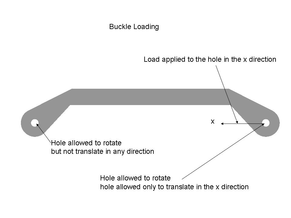
Attached you will find a gerneral picture of what I'm trying to do.
May 07, 2010
02:06 PM
- Mark as New
- Bookmark
- Subscribe
- Mute
- Subscribe to RSS Feed
- Permalink
- Notify Moderator
May 07, 2010
02:06 PM
Unfortunately MECHANICA can only use small deflection theory for buckling.
Stiffness is calculated in the initial state and the analysis calculates
stability from that point. You will need to have a point at the center of
the hole fixed in YZ, free in X and connected with rigid links to the hole.
---Jim Holst
Stiffness is calculated in the initial state and the analysis calculates
stability from that point. You will need to have a point at the center of
the hole fixed in YZ, free in X and connected with rigid links to the hole.
---Jim Holst
May 10, 2010
03:22 PM
- Mark as New
- Bookmark
- Subscribe
- Mute
- Subscribe to RSS Feed
- Permalink
- Notify Moderator
May 10, 2010
03:22 PM
Thanks to Jim, Mark, and Paul.
Creating a point at the center of the hole and applying a rigid constraint from the point to the hole surface worked. But my results are not looking quite right. The fixed end grows in size when I animate the results.
Anyone have any ideas as to what might be causing this?
Se avi file attached
Creating a point at the center of the hole and applying a rigid constraint from the point to the hole surface worked. But my results are not looking quite right. The fixed end grows in size when I animate the results.
Anyone have any ideas as to what might be causing this?
Se avi file attached
May 11, 2010
03:37 AM
- Mark as New
- Bookmark
- Subscribe
- Mute
- Subscribe to RSS Feed
- Permalink
- Notify Moderator
Jan 30, 2016
01:37 PM
- Mark as New
- Bookmark
- Subscribe
- Mute
- Subscribe to RSS Feed
- Permalink
- Notify Moderator
Jan 30, 2016
01:37 PM
Hi Jonathan,
even if is passed about 6 years, I would to ask you to explain this phenomenon.
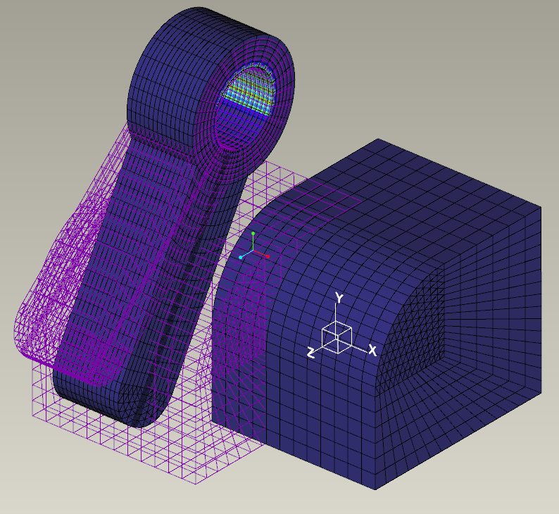
I've a similar problem: I want to rotate a drum around its axial hole, imposing the angular displacement. All of this in a LDA (large deformation analysis) in Creo 3.
What happen is that during the rotation the drum grows radially and the stresses are very high even if there are no load, only a rotation imposed around a hole used like a pin.
Feb 01, 2016
03:53 AM
- Mark as New
- Bookmark
- Subscribe
- Mute
- Subscribe to RSS Feed
- Permalink
- Notify Moderator
Feb 01, 2016
03:53 AM
That's surprising if you're using LDA - I would have expected that to work correctly. Maybe it doesn't adjust the direction of loads (or specifically enforced displacements) during the Large Displacement calculations...
Can you share some more details of your model set-up?
Has anyone else tried this kind of analysis?
Feb 01, 2016
05:17 AM
- Mark as New
- Bookmark
- Subscribe
- Mute
- Subscribe to RSS Feed
- Permalink
- Notify Moderator
Feb 01, 2016
05:17 AM
Of course, but the trial assembly is made in Creo 3.
It's ok?
I can redo it into WF5/Creo Eelements if you prefer.
Feb 01, 2016
05:58 AM
- Mark as New
- Bookmark
- Subscribe
- Mute
- Subscribe to RSS Feed
- Permalink
- Notify Moderator
Feb 01, 2016
05:58 AM
It looks like I've got access to a Creo 3 install, so go ahead 
Feb 01, 2016
08:03 AM
- Mark as New
- Bookmark
- Subscribe
- Mute
- Subscribe to RSS Feed
- Permalink
- Notify Moderator
Feb 01, 2016
08:03 AM
Here it is.
There are not the results' folders because they're much big.
Feb 01, 2016
11:29 AM
- Mark as New
- Bookmark
- Subscribe
- Mute
- Subscribe to RSS Feed
- Permalink
- Notify Moderator
Feb 01, 2016
11:29 AM
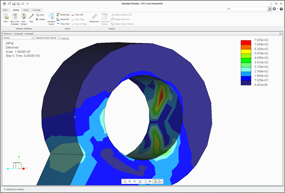
Wow, that takes a while to converge - three loadsteps took just over 7000 CPU seconds on my reasonably fast Xeon!
Anyway, that seems strange. If there's any radial growth I can't see it, but the strain energy measure and the shear stress plot suggest that the pin constraint is trying to resist the rotation. The part is stiff compared to the load, and you can see all the elements rotating around the pin, but the stresses in the arm suggest that it is bending slightly.
Interestingly, the pin constraint version produced errors about
"The rotational component of a specified constraint will have no effect because the surface to which it is applied is not associated with any shells";
when I replaced it with an explicit constraint using the cylindrical csys, those errors did not appear, but the results looked the same (which makes sense, if the rotational components are being ignored).
I tried replacing the constraint with a weighted link and advanced spring, but LDA doesn't allow links or advanced springs!
I wonder whether the Large Displacements are not correctly implemented in the constraint - particularly when the constraint is cylindrical. This looks like a bug - it might be time to submit it to Support, I would think...
Where are Charles Simpson and Mats Lindqvist? 
Feb 01, 2016
12:50 PM
- Mark as New
- Bookmark
- Subscribe
- Mute
- Subscribe to RSS Feed
- Permalink
- Notify Moderator
Feb 01, 2016
12:50 PM
I report a video of PTC where you can see a "big linear displacement" and a contact.
I want to make the same but into a "rotational version".
I've also tried with a "simple constraint with a cylindrical coordinate system (the constraint "spinta" within the ConstrainSet 1) but it didn't work.
Feb 02, 2016
03:19 AM
- Mark as New
- Bookmark
- Subscribe
- Mute
- Subscribe to RSS Feed
- Permalink
- Notify Moderator
Feb 02, 2016
03:19 AM
Hi Jonathan, This original post is from 2010, so I have not seen it until now. I'll see if I have time to look further into it.
Feb 02, 2016
05:13 AM
- Mark as New
- Bookmark
- Subscribe
- Mute
- Subscribe to RSS Feed
- Permalink
- Notify Moderator
Feb 02, 2016
05:13 AM
Still haven't finished the Christmas homework Mats gave us ...
Feb 02, 2016
05:20 AM
- Mark as New
- Bookmark
- Subscribe
- Mute
- Subscribe to RSS Feed
- Permalink
- Notify Moderator
Feb 02, 2016
05:20 AM
He has finite friction switched on.
Multiply the analysis run time by 100.
Feb 02, 2016
05:37 AM
- Mark as New
- Bookmark
- Subscribe
- Mute
- Subscribe to RSS Feed
- Permalink
- Notify Moderator
Feb 02, 2016
05:37 AM
Hi Charles,
I don't think it's the classic visualisation issue, as he's running with LDA (and visually the rotation seems good).
Finite friction is set within the contacts, correct? It shouldn't affect a test with a single component and a pin or cylindrical constraint...
Cheers,
Jonathan
Feb 02, 2016
06:34 AM
- Mark as New
- Bookmark
- Subscribe
- Mute
- Subscribe to RSS Feed
- Permalink
- Notify Moderator
Feb 02, 2016
06:34 AM
Hi,
I see you are using enforced displacements called 'spinta' and 'spinta_spigolo'
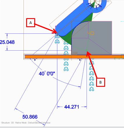
'spinta' rotates 40deg and buries half of the blue part in the block
'spinta_spigolo' and 'spinta_spigolo_3' move the point on the end of the blue part -44.271 in the Z direction which buries half the blue part in the block.
Additionally 'spinta_spigolo_3' Y movement of -25.048 will probably 'fight' the cylindrical constraint.
Then you are using LDA and the RAMP function...
LDA very costly in terms of time (and doesn't use all the potential CPU) and most useful solutions are linear (and makes better use of CPU). LDA for strains > approx. 5%. Movement of the structure can be much bigger and does not require LDA. What would matter for a large 'structural movement' is whether a force's direction remains the same relative to the world or the surface to which it is applied. (pressures follow structure, forces follow the WCS or UCS)
The RAMP function solves the problem with your enforced displacements multiplied by 0 (zero) and then solves the problem with your enforced displacements multiplied by 1 (one). In the second part of the solution the blue part is moved the full distance and immediately buried in the block. The solver will struggle and then probably fail.
Questions
Why do you need it to move so far before contact?
The cylindrical constraint is frictionless (whether made using a pin constraint or displacement constraint in radial csys) and there is nothing to resist the motion until contact with the block.
Why did you include 'snap through' in two of your analyses?
Notes
The cylindrical constraint (however made) is infinitely stiff and the cylindrical hole will remain a perfect circle (Its length may change). This hole may be over constrained if results close to the pin are important. I would propose modelling a pivot with a contact to permit a more 'realistic' movement of material.
This model looks like you could exploit symmetry (would make it easier to constrain)
Put the blue part in initial contact with the block and deselect 'Maximum initial interpenetration' in the analysis definition form
Switch off finite friction until everything is working properly. (you will surprise at how little the difference in result will be)
Switch off LDA until everything is working properly
If the blue part must approach the block then use smaller steps rather than the system RAMP function. But this is only if the blue part has to 'approach'. You probably won't need it if you are in initial contact. Bear in mind that if you do use finer steps to bring the blue part into contact then there is a possibility that the surfaces will 'miss'. This happens when a subsequent time step 'buries' one part in another. For this select 'Maximum initial interpenetration' and set it to a value that is approximately equal to the displacement in a time step.
Have fun.
Feb 02, 2016
07:20 AM
- Mark as New
- Bookmark
- Subscribe
- Mute
- Subscribe to RSS Feed
- Permalink
- Notify Moderator
Feb 02, 2016
07:20 AM
Giulio,
Just spotted that you have 60 intervals defined in the output tab of the analysis definition form for 2 of your analyses and 10 in the other 2. (I would have used a user defined time step function. I remain confused over the apparent overlap of these two options)
Also, I don't think my assy loaded with the parts in the correct positions. But from you image above, the blue part still looks buried if rotated 40deg or translated the prescribed amount.
Do you have a more up to date assy?
Thanks
Charles
Feb 02, 2016
09:27 AM
- Mark as New
- Bookmark
- Subscribe
- Mute
- Subscribe to RSS Feed
- Permalink
- Notify Moderator
Feb 02, 2016
09:27 AM
They are all tests.
I have tried with vary time steps, at each time step both on "Auto" that on "User defined".
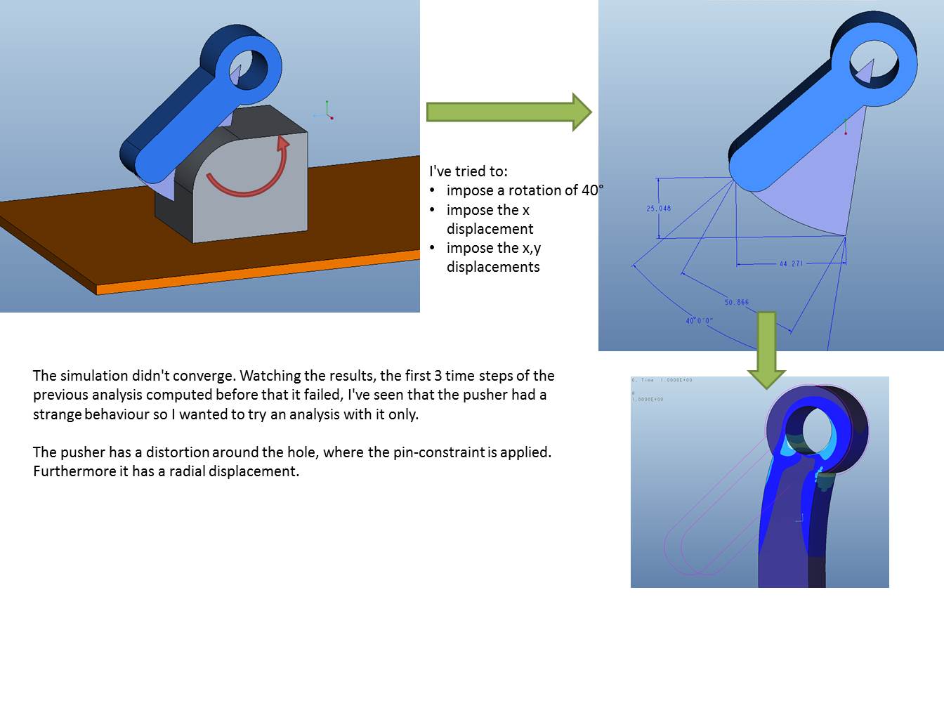
The true is that I still don't know how to do. Now, while I'm writing, I've launched an analysis expressed in thez picture.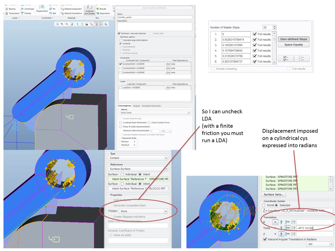
One hour ago I tried the same analysis with only the blu part (without contact and LDA).
It went, but the rotation it wasn't correct but much more little.
The 7z file attached is a cleaned assembly with the last attempt that I've described.
Feb 02, 2016
08:53 AM
- Mark as New
- Bookmark
- Subscribe
- Mute
- Subscribe to RSS Feed
- Permalink
- Notify Moderator
Feb 02, 2016
08:53 AM
My question to Charles outside the main argument: you've said "LDA very costly in terms of time (and doesn't use all the potential CPU)". It seems to me that my workstation utilizes all the cpu during LDA.
Answer 1
"Why do you need it to move so far before contact?"
If you resume the part "blocco" you'll see that the two parts are closer.
In the analysis I focused on the pin constraint and on why it creates tension.
Answer 2
"Why did you include 'snap through' in two of your analysis?"
Is a forgetfulness of a previous analysis. Anyway I don't think it has any effect on an analysis where there are only enforced displacements.
I don't understand this part: "In the second part of the solution the blue part is moved the full distance and immediately buried in the block. The solver will struggle and then probably fail."
You speak of the function RAMP like you didn't set some number of master step in the tab OUTPUT. I'm wrong?
Feb 02, 2016
09:15 AM
- Mark as New
- Bookmark
- Subscribe
- Mute
- Subscribe to RSS Feed
- Permalink
- Notify Moderator
Feb 02, 2016
09:15 AM
Giulio Fraulini wrote:
My question to Charles outside the main argument: you've said "LDA very costly in terms of time (and doesn't use all the potential CPU)". It seems to me that my workstation utilizes all the cpu during LDA.
Are you sure (~100% CPU Usage)? Or is it just sharing one thread (13% or 25%) across all the cores?
A good measure in Mechanica is to compare Total CPU Time with Total Elapsed Time. On the run I've just tried, CPU Time is ~ 2× Elapsed Time - so it was able to use (all) 4 cores for some of the run.
"Why did you include 'snap through' in two of your analysis?"
Is a forgetfulness of a previous analysis. Anyway I don't think it has any effect on an analysis where there are only enforced displacements.
The main influence is to slow down the convergence - on my system it reduced from ~7000 sec CPU time, to ~1000 after disabling snap-through detection!
Feb 02, 2016
09:51 AM
- Mark as New
- Bookmark
- Subscribe
- Mute
- Subscribe to RSS Feed
- Permalink
- Notify Moderator
Feb 02, 2016
09:51 AM
Guilio,
I will check my CPU usage.
The gap : you don't need it, it is of no use. It slows you up.
timestep function vs master steps. I saw that you had 60 master steps after my earlier post. As far as I know, timesteps in the load function and these master intervals fulfil the same objective. Does the functionality overlap or are there differences I have never appreciated. Can someone clarify why we have both?
Can you clarify ... you are trying to move the end of the blue part from its initial position at A to its final position at B using the enforced displacement applied to the end of the blue part at A. Thus causing the blue part (with properties similar to copper) to push the block along the surface against friction?
There is an earlier discussion on here about finite friction requiring very very very fine time steps (and some other work around) to get sensible answers. Perhaps this is where the problem is?
Also I wonder that having X and Y being varied or scaled by the same function cannot be true as the motion is circular. The initial and final positions may be correct but intermediate positions are not. Therefore you must use theta to step the study.
Thanks
Feb 02, 2016
10:32 AM
- Mark as New
- Bookmark
- Subscribe
- Mute
- Subscribe to RSS Feed
- Permalink
- Notify Moderator
Feb 02, 2016
10:32 AM
"you are trying to move the end of the blue part from its initial position at A to its final position at B using the enforced displacement applied to the end of the blue part at A. Thus causing the blue part (with properties similar to copper) to push the block along the surface against friction?" Yes.
But the thing has been interrupted before because the blue part did not move correctly. So I only studied the movement of the blu part.
I tried to move the blue part into three manners:
1) enforcing angular displacement
The most obvious thing to do but it doesn't work and I don't know why.
2) enforcing horizontal displacement
if the part has a pin at the top, it has only 1 dof; so a singular X or Y displacement might work. No, it doesn't work
3) enforcing horizontal and vertical displacement
even if I think it is not correct, I tried...
In all this three cases the hole of the pin on the blue part deforms.
I've always tried with LDA thinking it was correct given the large displacements of the parts in the model. Now I'm trying as Charles suggested without LDA.
Feb 02, 2016
10:44 AM
- Mark as New
- Bookmark
- Subscribe
- Mute
- Subscribe to RSS Feed
- Permalink
- Notify Moderator
Feb 02, 2016
10:44 AM
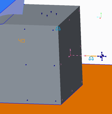
Well, that version has solved for me in three (large!) steps - the only odd thing is that the block seems to be moving sideways.
You've used a 'planar' constraint on the bottom face of the block; I would have tried an explicit constraint in X and Y, with Z free (assuming that's what you're trying to simulate.
Just thought I'd let you know in case you want to change that before solving all 20 loadsteps...
Feb 02, 2016
11:17 AM
- Mark as New
- Bookmark
- Subscribe
- Mute
- Subscribe to RSS Feed
- Permalink
- Notify Moderator
Feb 02, 2016
11:17 AM
Do you have used the file that I updated one hour ago?
I just finished that simulation but I think it's not good...
Now I try again, removing the "planar constraint and putting an x,y constraint with Z free as you suggested.
Feb 03, 2016
08:40 AM
- Mark as New
- Bookmark
- Subscribe
- Mute
- Subscribe to RSS Feed
- Permalink
- Notify Moderator
Feb 03, 2016
08:40 AM
Guilio,
The UK's internet died yesterday and am busy now. But as lunchtime meanderings I summarise what I did below if any help.
Jonathan got further than me. Can you upload your model?
Following the process of 'simplify simplify simplify until it works then gradually make it more complex as we build up confidence'
I adjusted your model as follows:
- Rebuilt the assy without constraining using connections
- Removed all finite friction. Contacts are now frictionless.
- Removed all your mesh controls and volume regions and made it mesh with very few tetrahedral elements (might be poor answers but we know they work)
- As Jonathan noted, I found and removed the planar constraint on the underside of the block (I can't see sure how the software works out what would happen between this and the contact).
- Put planar constraints either side of the block to guide it when pushed. I did not use the planar constraint I used the displacement constraint (we know these work)
- To stop the block from moving back freely : In the block I created 2 datum points behind the back surface, a weighted link to the back surface from one, a simple spring (1000N/mm) between the points and fully constrain the point furthest away (including rotations else the spring spins)
- Create a spring force measure.
- Created a cylindrical csys for the blue part.
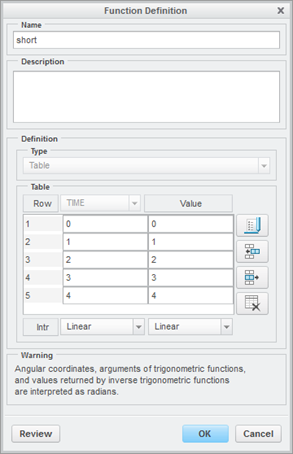
- Created a cylindrical constraint for the pin joint with an Theta enforced displacement of '-1' only. Should be degrees right? (note I did not check the 'interpret as radians' check box)

- Created a timestep function to multiply the constraint
- Ran a SMALL deflection study and got the following silliness
(I could have used symmetry but forgot)

What's the block doing over there?
The pin joint isn't working properly. The inside cylindrical surface has various values of Theta and should all be 4deg in the final timestep.
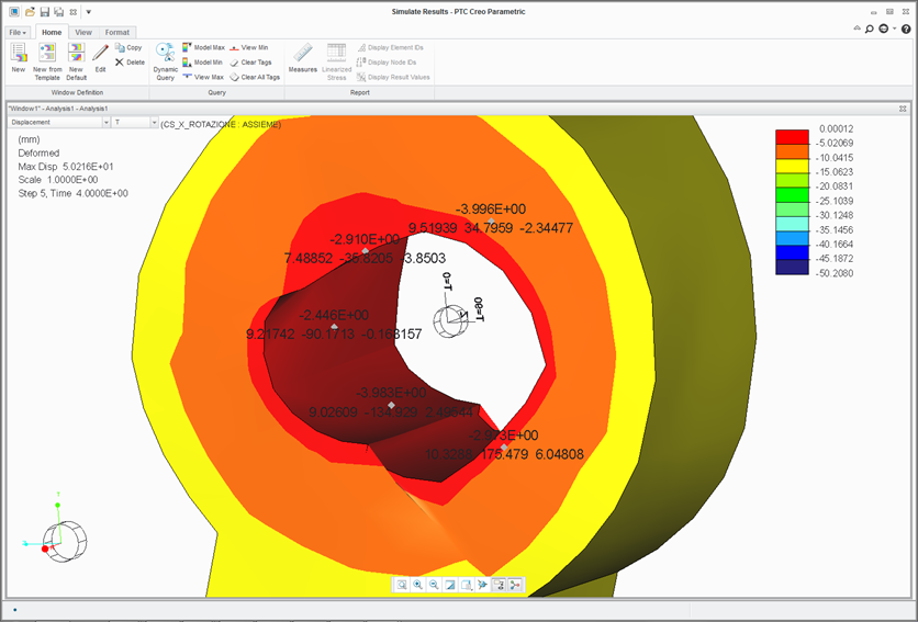
15. I then ran LDA and things seem much more sensible up to a point ...
Theta is good @ a value of '4'
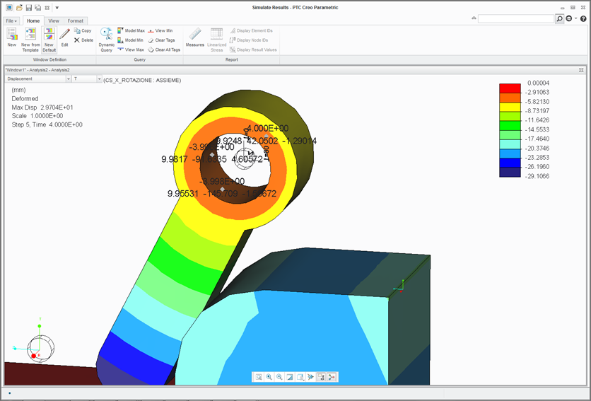
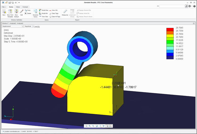
But displacement linear ... ?
22mm block movement from 4 degrees of rotation?
I would have expected about 3.5mm for 4 degs
The spring force measure comes out as 22kN; so that's working.
And anyway, we should be able to do this sum on paper. (or spreadsheet)
So is Theta degs or rads? I vaguely recall a thread on here about this somewhere.
22mm equates to about 26 degs or roughly half a radian
It can't be rads or the part would have rotated 230degs
At this point I ran out of time.
Can someone point out my error (fallible human)?
If not, I will raise a call or two
(Depending on your objective I would consider Mechanism Dynamics if you have access to it)
Atb.
Feb 04, 2016
06:10 AM
- Mark as New
- Bookmark
- Subscribe
- Mute
- Subscribe to RSS Feed
- Permalink
- Notify Moderator
Feb 04, 2016
06:10 AM
I wonder whether 'theta' (when not interpreted as radians) is actually some sort of linear measurement... Also, does free R with enforced theta constitute a pin constraint? (I think it probably does, just with any loads reacted tangentially rather than radially, but it's not immediately intuitive.)
In the results without LDA, has each surface boundary around the bore translated tangentially?
How did you make the LDA run with a link? When I tried a model with a link and LDA, it told me that links were not permitted.
Is your model showing any shear stress around the bore with an enforced theta (it certainly appears to with free theta...)?
Feb 05, 2016
05:05 AM
- Mark as New
- Bookmark
- Subscribe
- Mute
- Subscribe to RSS Feed
- Permalink
- Notify Moderator
Feb 05, 2016
05:05 AM
Jonathan,
Links and LDA,, I don't know! I will try in Creo 2.0 later.
I avoid using a ground springs by the '2 point, simple spring and constraint' method as LDA doesn't like ground springs. (even if suppressed)
Shear stress ...
There shouldn't be any.
I found this which vaguely rings a bell and explains the (mm) units in the displacement window
https://support.ptc.com/appserver/cs/view/solution.jsp?n=CS213943&source=minisearch
Displacement in the Theta Direction output the same value as linear Displacement in Creo Simulate
- Enforced displacement in the Theta θ direction in a cylindrical coordinate system is outputed as a linear displacement results
- How to get enforced displacement in the Theta θ direction reported as the Displaced Arc Length
- Creo Simulate 2.0 all datecodes
- Work to Product Specification of Creo Simulate
- Theta is interpreted in mm ( r * theta ) and not in deg/rad
- To find out the arc length create an advanced rigid links in the pin position as solid elements does not have rotational degrees of freedom
- Assign them an enforced rotation using of point, surface and advanced rigid links and apply an enforced rotation to central point the measures Disp_Mag_wcs ~= Arc length
Feb 05, 2016
08:35 AM
- Mark as New
- Bookmark
- Subscribe
- Mute
- Subscribe to RSS Feed
- Permalink
- Notify Moderator
Feb 05, 2016
08:35 AM
I raised a call about this rad/deg, unreasonable movement, shear stress question.
Feb 09, 2016
11:15 AM
- Mark as New
- Bookmark
- Subscribe
- Mute
- Subscribe to RSS Feed
- Permalink
- Notify Moderator
Feb 09, 2016
11:15 AM
Have you had some answer?
