
Turn on suggestions
Auto-suggest helps you quickly narrow down your search results by suggesting possible matches as you type.
Showing results for
Turn on suggestions
Auto-suggest helps you quickly narrow down your search results by suggesting possible matches as you type.
Showing results for
Community Tip - Did you get called away in the middle of writing a post? Don't worry you can find your unfinished post later in the Drafts section of your profile page. X
- Community
- Creo+ and Creo Parametric
- 3D Part & Assembly Design
- How do I change the line style for a cutting line?
Options
- Subscribe to RSS Feed
- Mark Topic as New
- Mark Topic as Read
- Float this Topic for Current User
- Bookmark
- Subscribe
- Mute
- Printer Friendly Page
How do I change the line style for a cutting line?
May 05, 2015
11:32 AM
- Mark as New
- Bookmark
- Subscribe
- Mute
- Subscribe to RSS Feed
- Permalink
- Notify Moderator
May 05, 2015
11:32 AM
How do I change the line style for a cutting line?
I am working on drawings and need to change the line weight of a cutting line through a cross section. I cannot change the cutting lines using the line style manager and I need a different line style that what is available with cutting_line options in the drawing properties. Is this option available with Creo 2.0?
This thread is inactive and closed by the PTC Community Management Team. If you would like to provide a reply and re-open this thread, please notify the moderator and reference the thread. You may also use "Start a topic" button to ask a new question. Please be sure to include what version of the PTC product you are using so another community member knowledgeable about your version may be able to assist.
Solved! Go to Solution.
Labels:
- Labels:
-
2D Drawing
1 ACCEPTED SOLUTION
Accepted Solutions
May 13, 2015
08:46 AM
- Mark as New
- Bookmark
- Subscribe
- Mute
- Subscribe to RSS Feed
- Permalink
- Notify Moderator
May 13, 2015
08:46 AM
If this is an assembly, you solution may be to use component display in the layout tab of the drawing. You can change the linestyle of components of an assembly.
In the drawing under the layout tab, component display, the menu manager pops up, select a component you want to show in phantom, select ok, select phantom transparent (or opaque, you have to experiment to see what work for you).
24 REPLIES 24
May 12, 2015
03:04 PM
- Mark as New
- Bookmark
- Subscribe
- Mute
- Subscribe to RSS Feed
- Permalink
- Notify Moderator
May 12, 2015
03:04 PM
I have been searching around for an option to map the cross section cut lines, not hatch lines, to another pen in the pen table but cant seem to find what I am looking for. Is it possible to map different types of lines to different pens?
May 12, 2015
05:00 PM
- Mark as New
- Bookmark
- Subscribe
- Mute
- Subscribe to RSS Feed
- Permalink
- Notify Moderator
May 12, 2015
05:00 PM
Take a look at these links:
http://support.ptc.com/cs/cs_27/howto/plt522/plt522.htm (maintenance required)
Cross section cutting lines follow the pen with "drawing_color". As far as I can tell they cannot be separated from geometry.
May 12, 2015
05:07 PM
- Mark as New
- Bookmark
- Subscribe
- Mute
- Subscribe to RSS Feed
- Permalink
- Notify Moderator
May 12, 2015
05:07 PM
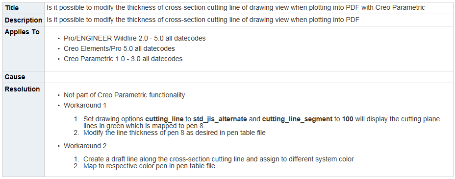
Actually, there is a workaround of sorts, but it's on a drawing by drawing basis:
https://support.ptc.com/appserver/cs/view/solution.jsp?n=CS94065
May 13, 2015
07:40 AM
- Mark as New
- Bookmark
- Subscribe
- Mute
- Subscribe to RSS Feed
- Permalink
- Notify Moderator
May 13, 2015
07:40 AM
Thanks Tom. I am going to try "Workaround 1" as this would probably suit my needs for this specific project/customer. I have tried Workaround 2 without great success, I don't know if I have a plotter file or setting that is off but even if I sketch over it the thick geometry line always seems to plot. For small simple details I have changed a view to draft entities to control the line style, only when the design is complete, but if any modifications are needed the view must be entirely recreated.
I will let you know how the workaround goes.
May 13, 2015
08:19 AM
- Mark as New
- Bookmark
- Subscribe
- Mute
- Subscribe to RSS Feed
- Permalink
- Notify Moderator
May 13, 2015
08:19 AM
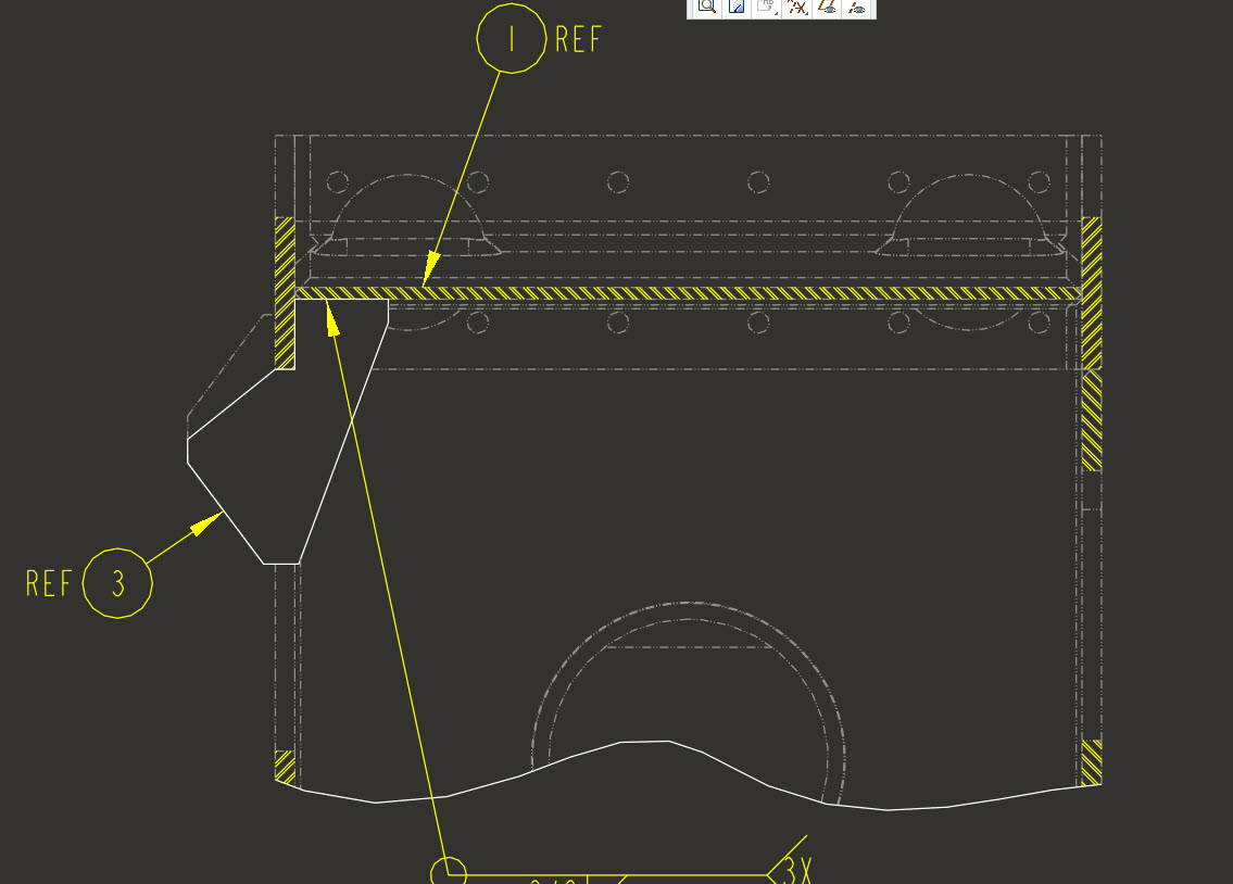
OK I must have stated what I was looking for incorrectly. While the workaround did change the cut line as stated that's not what I need to do. What I want to do is change the line type of the cut geometry. When we do drawings for a specific customer only items that are being covered in a sheet are to be shown in bold, geometry style, and everything else is a lighter line. Generally we just change the lines we don't want bold to highlight primary color which goes to pen 4 but I cant do this with cross section geometry.
A simple example would be...Lets say I had a model of a outhouse and wanted to make a drawing illustrating the toilet. I would probably have a plan view on the drawing where I have a cross section cutting the roof off so I can see inside the outhouse. I would like to show only the toilet in geometry line style, pen 1, and have everything that has nothing to do with the toilet plot as another thickness, we use pen 4 by selecting highlight primary as the color. My issue is I can change any and all lines in that view except for the cut geometry lines. Is it possible to change the cut geometry line style?
May 13, 2015
08:46 AM
- Mark as New
- Bookmark
- Subscribe
- Mute
- Subscribe to RSS Feed
- Permalink
- Notify Moderator
May 13, 2015
08:46 AM
If this is an assembly, you solution may be to use component display in the layout tab of the drawing. You can change the linestyle of components of an assembly.
In the drawing under the layout tab, component display, the menu manager pops up, select a component you want to show in phantom, select ok, select phantom transparent (or opaque, you have to experiment to see what work for you).
May 13, 2015
09:22 AM
- Mark as New
- Bookmark
- Subscribe
- Mute
- Subscribe to RSS Feed
- Permalink
- Notify Moderator
May 13, 2015
09:22 AM
For the example I posted this worked, changed user color, but for some reason I went to another sheet in the drawing to change the component display, same component, and it had no effect on the cut geometry, but did change everything else.
Aug 23, 2016
09:39 AM
- Mark as New
- Bookmark
- Subscribe
- Mute
- Subscribe to RSS Feed
- Permalink
- Notify Moderator
Aug 23, 2016
09:39 AM
Hi Williams,
What if I have a part and not an assembly, how do I change the boundary lines of my drawing (view) in cross section? Already I tried everything without success.
Thanks
Aug 23, 2016
09:56 AM
- Mark as New
- Bookmark
- Subscribe
- Mute
- Subscribe to RSS Feed
- Permalink
- Notify Moderator
Aug 23, 2016
09:56 AM
Did you try the config.pro option Jacob found in the post below? With just a part, you can change edges using the edge display icon in the layout tab. Not sure about the edges of a cross section though or especially of the boundary edges , I have never needed to do that.
Drawing properties>detail options>crossec_type - ours is set to "new_style" I changed to "old style".
Now everything appears follow the settings in the component display settings. I'm not sure exactly what functionality will change with the old vs. new style but I am assuming that it is just how Creo looks at the cross section, cut vs. z clipping, and I don't think I will notice the difference.
Aug 23, 2016
10:24 AM
- Mark as New
- Bookmark
- Subscribe
- Mute
- Subscribe to RSS Feed
- Permalink
- Notify Moderator
Aug 23, 2016
10:24 AM
Thanks for the information Williams, but does not work any of the options when we have a cutaway view 😞 I give up. rsrsrs
Aug 23, 2016
10:30 AM
- Mark as New
- Bookmark
- Subscribe
- Mute
- Subscribe to RSS Feed
- Permalink
- Notify Moderator
Aug 23, 2016
10:30 AM
Can you add a screenshot of what the problem is? Maybe I'm missing the real problem.
Aug 23, 2016
10:41 AM
- Mark as New
- Bookmark
- Subscribe
- Mute
- Subscribe to RSS Feed
- Permalink
- Notify Moderator
Aug 23, 2016
10:41 AM
Follows the image...
Aug 23, 2016
12:31 PM
- Mark as New
- Bookmark
- Subscribe
- Mute
- Subscribe to RSS Feed
- Permalink
- Notify Moderator
Aug 23, 2016
12:31 PM
I've never had the need to do that. I can't even think of a way to do it other than adding a sketch to your model and setting the sketch line properties so they show as desired.
You may try posting this as a separate question here on the forum. Also use a clearer picture might help.
May 13, 2015
08:21 AM
- Mark as New
- Bookmark
- Subscribe
- Mute
- Subscribe to RSS Feed
- Permalink
- Notify Moderator
May 13, 2015
08:21 AM
Can you add an image of what you are trying to accomplish? I thought Tom was on the right track till I read your last post. If you are having to convert an entire view to draft entities to get what you want, there is definitely something we are not understanding.
May 13, 2015
08:44 AM
- Mark as New
- Bookmark
- Subscribe
- Mute
- Subscribe to RSS Feed
- Permalink
- Notify Moderator
May 13, 2015
08:44 AM
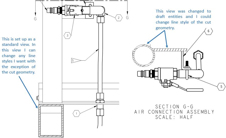
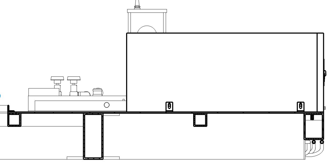
Here you go. This shows a couple of small details were I am calling out some parts for a compressed air quick disconnect. I only want my pen 1 geometry line style for the compressed air components with other items, in this case framing and other items, set to a different line width. In these details the cross section geometry wouldn't take anything away from the design intent but the customer wants only items relevant to that sheet in bold.
I suppose that I could change my pen 1 to a lighter line and bold non-cut items but that could be a pain depending on the drawing. It would just be nice if we had control over any line in a drawing.
May 13, 2015
09:24 AM
- Mark as New
- Bookmark
- Subscribe
- Mute
- Subscribe to RSS Feed
- Permalink
- Notify Moderator
May 13, 2015
09:24 AM
I replied to the wrong post (see above). This is exactly what we use component display for. It uses phantom lines instead of light lines though.
May 13, 2015
09:57 AM
- Mark as New
- Bookmark
- Subscribe
- Mute
- Subscribe to RSS Feed
- Permalink
- Notify Moderator
May 13, 2015
09:57 AM
As stated in the previous post it worked exactly as you said on the example pic. I ran through the same procedure for this view and the framing/flooring I cut through did not change display, but everything else did in its assembly. Any clue to why this is?
May 13, 2015
10:11 AM
- Mark as New
- Bookmark
- Subscribe
- Mute
- Subscribe to RSS Feed
- Permalink
- Notify Moderator
May 13, 2015
10:11 AM
Hmmm, I can't recreate the problem so I'm not sure. I do remember having some visibility issues with component display in the past but I'm sure it didn't have anything to do with x-sections. Mostly when I had issues I attributed it to me selecting sub-level components and assemblies instead of top levels or visa-versa.
Not sure how I would troubleshoot it other than creating a few views of the same thing and attempting different selections on each to see if I could figure out the best way to get what I wanted.
May 13, 2015
11:09 AM
- Mark as New
- Bookmark
- Subscribe
- Mute
- Subscribe to RSS Feed
- Permalink
- Notify Moderator
May 13, 2015
11:09 AM
I think I figured out my problem...
Drawing properties>detail options>crossec_type - ours is set to "new_style" I changed to "old style".
Now everything appears follow the settings in the component display settings. I'm not sure exactly what functionality will change with the old vs. new style but I am assuming that it is just how Creo looks at the cross section, cut vs. z clipping, and I don't think I will notice the difference.
Thanks to everyone who chimed in on this and got me in the right direction, you have saved me a lot of time and headache!
May 13, 2015
11:13 AM
- Mark as New
- Bookmark
- Subscribe
- Mute
- Subscribe to RSS Feed
- Permalink
- Notify Moderator
May 13, 2015
11:13 AM
That's funny because I was just noticing that setting and wondering what it did.
Glad you got it working.
May 13, 2015
10:28 AM
- Mark as New
- Bookmark
- Subscribe
- Mute
- Subscribe to RSS Feed
- Permalink
- Notify Moderator
May 13, 2015
10:28 AM
We use this exact same approach in certain assemblies when components are reused. Sometimes the component display doesn't seem to work correctly. Try resetting all components back to "standard". Also try using edge display and reset all edges back to "default". If those don't work, try creating a completely new view and see if it responds any better.
May 13, 2015
10:56 AM
- Mark as New
- Bookmark
- Subscribe
- Mute
- Subscribe to RSS Feed
- Permalink
- Notify Moderator
May 13, 2015
10:56 AM
I am not sure what the issue is. I even went and opened up different models and made some quick views without any luck. The component display settings do not make any adjustment to the cut geometry but the rest of the geometry follows as expected, even if I pick the top assembly everything works as expected except for the cut stuff.
May 15, 2015
10:38 AM
- Mark as New
- Bookmark
- Subscribe
- Mute
- Subscribe to RSS Feed
- Permalink
- Notify Moderator
May 15, 2015
10:38 AM
I regularly have to create a new view to resolve display issues when revising drawings. As stated, changing the view properties, etc does not change the display I'm attempting to correct. Thanks to everyone for the additional tips! Always happy to add to my toolbox 
May 13, 2015
09:16 AM
- Mark as New
- Bookmark
- Subscribe
- Mute
- Subscribe to RSS Feed
- Permalink
- Notify Moderator
May 13, 2015
09:16 AM
Hi,
IMPORTANT NOTE:
---
To enable 8 pen configuration, you have to add the following option into config.pro file:
use_8_plotter_pens yes
By default, Creo uses 4 pens, only.
Martin Hanak
Martin Hanák
