
Turn on suggestions
Auto-suggest helps you quickly narrow down your search results by suggesting possible matches as you type.
Showing results for
Turn on suggestions
Auto-suggest helps you quickly narrow down your search results by suggesting possible matches as you type.
Showing results for
Community Tip - Want the oppurtunity to discuss enhancements to PTC products? Join a working group! X
- Community
- Creo+ and Creo Parametric
- 3D Part & Assembly Design
- Mesh Question
Options
- Subscribe to RSS Feed
- Mark Topic as New
- Mark Topic as Read
- Float this Topic for Current User
- Bookmark
- Subscribe
- Mute
- Printer Friendly Page
Mesh Question
May 07, 2015
03:50 AM
- Mark as New
- Bookmark
- Subscribe
- Mute
- Subscribe to RSS Feed
- Permalink
- Notify Moderator
May 07, 2015
03:50 AM
Mesh Question
Hi,
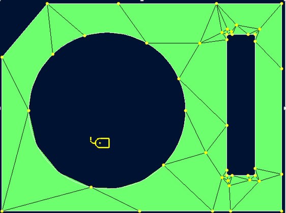
Looking for some advice or clarification that I understand how Mechanica works with respect to meshing.I have created a simple test part shown below and gone through many of the mesh settings to understand the influence they have. Note I am using Wildfire 4.0.
My question is, is the default mesh shown below on the top sufficient?
I understand Mechanica uses the p-element method which means a mesh can be coarse and results are obtained by increasing the order of equations until convergence is achieved, so I think this mesh is OK?
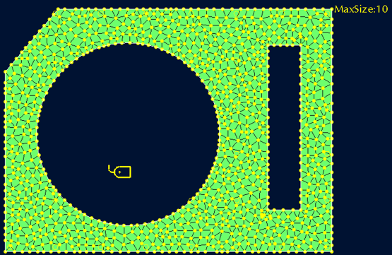
I am working with some people who used to different programs and they desire that I create a more uniform mesh - kind of like I have created in the bottom picture by limiting the max element size. But is this approach good practice with mechanica? I guess it would significantly increase the analysis time?
If anyone can give some advice and let me know if I am understanding this correctly it would be much appreciated.
Thanks
This thread is inactive and closed by the PTC Community Management Team. If you would like to provide a reply and re-open this thread, please notify the moderator and reference the thread. You may also use "Start a topic" button to ask a new question. Please be sure to include what version of the PTC product you are using so another community member knowledgeable about your version may be able to assist.
Labels:
- Labels:
-
General
6 REPLIES 6
May 07, 2015
10:38 AM
- Mark as New
- Bookmark
- Subscribe
- Mute
- Subscribe to RSS Feed
- Permalink
- Notify Moderator
May 07, 2015
10:38 AM
Hi s,
The best way to answer your question "is it sufficient" is to run an analysis using Multi-Pass Adaptive, and look at the convergence graph. If it levels off smoothly before reaching 9th order, the mesh is sufficient; if it's still climbing (or oscillating) then a finer mesh is needed.
Using a maximum element size as you've shown is rather a blunt tool. I much prefer to use Edge Length by Curvature (which can be applied to the whole part, or to selected geometry) which varies the size in proportion to the geometry radius. The default value of 2 is pretty good; 1.5 or 1.0 is usually overkill. This produces a more efficient mesh, with smaller elements only where they're needed.
In general, Mechanica is pretty fast to run so I tend to use SPA but make the mesh better than I think is necessary - so an ELC of 1.5 or lower in the areas I'm concerned about, or globally if it's a simple model.
If your H-element colleagues complain about the rapid mesh transitions Mechanica can use, just tell them that you'll use small elements everywhere if they'll run their models using 9th-order elements!
HTH!
May 07, 2015
10:47 AM
- Mark as New
- Bookmark
- Subscribe
- Mute
- Subscribe to RSS Feed
- Permalink
- Notify Moderator
May 07, 2015
10:47 AM
It looks like your model is not that big, so run an analysis for each mesh, and compare the results. Then show the results to your colleagues. And post a copy here 
May 08, 2015
01:52 AM
- Mark as New
- Bookmark
- Subscribe
- Mute
- Subscribe to RSS Feed
- Permalink
- Notify Moderator
May 08, 2015
01:52 AM
Thanks for the response guys. I'll pay close attention to the convergence graph in my analysis.
Appreciate the 'Edge Length by Curvature' advice also.
I'm going to be doing this on a much much more complex assembly so will put it into practice then. With this simple model computation time is so quick that its hard to see effects of different approaches yet.
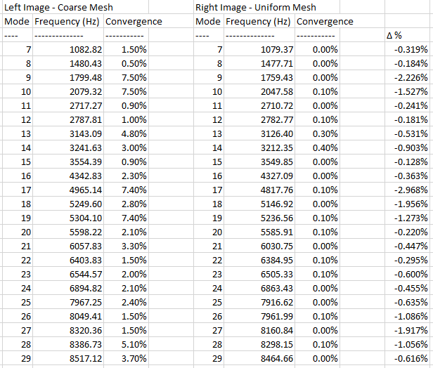
For an unconstrained modal analysis I got the following results. They have very similar mode frequencies (as expected) and the convergence seems better?
May 11, 2015
02:46 AM
- Mark as New
- Bookmark
- Subscribe
- Mute
- Subscribe to RSS Feed
- Permalink
- Notify Moderator
May 11, 2015
02:46 AM
For modal analysis the mesh size is much less of an issue than for stress analysis. Basically you only need to get the stiffness and mass distribution right, so for most parts (in H-elements) any 2nd order mesh will do.
I suspect you will see larger differences in stress analysis (if you will be doing any?)
May 08, 2015
07:51 AM
- Mark as New
- Bookmark
- Subscribe
- Mute
- Subscribe to RSS Feed
- Permalink
- Notify Moderator
May 08, 2015
07:51 AM
As Jonathand mentioned, run a MPA-analysis, create measures of the quantities you are interested in, and see how those converges as the P-level is increased. If a mesh is "sufficiently dense" is difficult to say; every model is unique. Beware of singularities; you have some sharp reentrant corners in your model that may not converge.
The default mesh settings are, so I've heard, is a compromise between solution acccuracy, meshing time, and solution time. My experience is that for geometries that are very simple, like a square, or a square block, the mesh becomes too coarse. If the geometry is more complex, then the mesh becomes finer automatically.
/Mats L/
May 08, 2015
08:19 AM
- Mark as New
- Bookmark
- Subscribe
- Mute
- Subscribe to RSS Feed
- Permalink
- Notify Moderator
May 08, 2015
08:19 AM
In that case also demand of your colleagues that they do the same, so decrease mesh size and compare results for each mesh size. If the results no longer change it shows that the mesh size is okay. (This is what all the text books say one should do, but in practice I've rarely seen this done).
