
Turn on suggestions
Auto-suggest helps you quickly narrow down your search results by suggesting possible matches as you type.
Showing results for
Turn on suggestions
Auto-suggest helps you quickly narrow down your search results by suggesting possible matches as you type.
Showing results for
Community Tip - Visit the PTCooler (the community lounge) to get to know your fellow community members and check out some of Dale's Friday Humor posts! X
- Community
- Creo+ and Creo Parametric
- 3D Part & Assembly Design
- How to enter EDIT mode?
Options
- Subscribe to RSS Feed
- Mark Topic as New
- Mark Topic as Read
- Float this Topic for Current User
- Bookmark
- Subscribe
- Mute
- Printer Friendly Page
How to enter EDIT mode?
Jun 17, 2015
10:55 AM
- Mark as New
- Bookmark
- Subscribe
- Mute
- Subscribe to RSS Feed
- Permalink
- Notify Moderator
Jun 17, 2015
10:55 AM
How to enter EDIT mode?
Hi everyone!
I'm having problems with Creo Schematics 3.0. I'd like to make a shape to an interconnect diagram connector(or any other artifacts), and in the shape editing process I'd like to fillet the corners of the rectangle I've made, but I can't. Creo says: "error, operation only valid in edit mode". I can't find a way to enter EDIT mode, how is it possible? I'm having quite similar problems with central catalog, I cant edit existing items in the catalog, because they are in the central catalog. I've read something about password protected designs, that if I enter the password I become an editor of the central catalog, but I didn't find any way to make a password protected design. Please help me find out how to do these settings.
Regards
Lac
This thread is inactive and closed by the PTC Community Management Team. If you would like to provide a reply and re-open this thread, please notify the moderator and reference the thread. You may also use "Start a topic" button to ask a new question. Please be sure to include what version of the PTC product you are using so another community member knowledgeable about your version may be able to assist.
Solved! Go to Solution.
Labels:
- Labels:
-
Routed Syst. Design
1 ACCEPTED SOLUTION
Accepted Solutions
Jun 17, 2015
12:52 PM
- Mark as New
- Bookmark
- Subscribe
- Mute
- Subscribe to RSS Feed
- Permalink
- Notify Moderator
Jun 17, 2015
12:52 PM
Lac
The following process in the Basic Tutorial
In the graphics window, double-click on the corner. The line enters edit mode.
From the edit line group, click Fillet.
In the bottom right below the graphics areas, edit the Radius to 3 and click the green tick
To password protect a design the information is available in the Read this first - i have extracted the relevant text for your convenience,
Within the PTC Creo Schematics installation, the system administrator can run a command-line program to password-protect the base design.
Open a command window and browse to the folder where password.exe is typically located:
<creoschematics_loadpoint>\i486_nt\creoschematics\bin
Enter password set <path to design—including the design folder> <password>.
In the following example, PTC Creo Schematics is installed at <creoschematics_loadpoint>.
The design that requires password protection is at <design_location>Project1.
The password that is set to the base design (Project1) is Creo.
- Open a command window and browse to the bin directory:
<creoschematics_loadpoint>\i486_nt\creoschematics\bin
- b. At the prompt, type the following command:
password set <design_location>\Project1 Creo
A system message confirms that the password has been set to Creo.
To unlock a design, open it in PTC Creo Schematics. Click Admin > Unlock catalog
and enter the password
Hope the above helps
Jim
4 REPLIES 4
Jun 17, 2015
12:52 PM
- Mark as New
- Bookmark
- Subscribe
- Mute
- Subscribe to RSS Feed
- Permalink
- Notify Moderator
Jun 17, 2015
12:52 PM
Lac
The following process in the Basic Tutorial
In the graphics window, double-click on the corner. The line enters edit mode.
From the edit line group, click Fillet.
In the bottom right below the graphics areas, edit the Radius to 3 and click the green tick
To password protect a design the information is available in the Read this first - i have extracted the relevant text for your convenience,
Within the PTC Creo Schematics installation, the system administrator can run a command-line program to password-protect the base design.
Open a command window and browse to the folder where password.exe is typically located:
<creoschematics_loadpoint>\i486_nt\creoschematics\bin
Enter password set <path to design—including the design folder> <password>.
In the following example, PTC Creo Schematics is installed at <creoschematics_loadpoint>.
The design that requires password protection is at <design_location>Project1.
The password that is set to the base design (Project1) is Creo.
- Open a command window and browse to the bin directory:
<creoschematics_loadpoint>\i486_nt\creoschematics\bin
- b. At the prompt, type the following command:
password set <design_location>\Project1 Creo
A system message confirms that the password has been set to Creo.
To unlock a design, open it in PTC Creo Schematics. Click Admin > Unlock catalog
and enter the password
Hope the above helps
Jim
Jun 19, 2015
03:14 AM
- Mark as New
- Bookmark
- Subscribe
- Mute
- Subscribe to RSS Feed
- Permalink
- Notify Moderator
Jun 19, 2015
03:14 AM
Hi Jim!
Thank you for your help, but I already found out what EDIT mode means, and how to set the password, from earlier discussions in the communities. I have to say this kind of graphics editing method is really obsolete and illogical. We purchased Creo Schematics because we are trying to decide which software should we use to design our block diagrams and wiring diagrams. Creo schematics would be a great and powerful software, but as I go further in the learning process, I feel like I'm using something from the mid 90's. There are lot's of things I cant find anywhere, for example this EDIT mode thing, there was nothing about this at all in the help center for example, and using this takes a lot of time from the designing process, but not just this, there are loads of things that are too complicated (nowadays there are methods to make things like this easier to use). Helpcenter should contain information about the password protection too, because it's really annoying to read: "Make a password protected design" if there is no explanation about it, OK I'd like to make one, but how?? (now I know how as I mentioned it before, but it took me 2 days to find it out). PTC should make it more user friendly, it would save lots and lots of time for designers. Anyway I still have some trust in the program, maybe we will be able to use it better than the other ones.
Thanks for your help again!
Regards
Lac
Jun 19, 2015
09:15 AM
- Mark as New
- Bookmark
- Subscribe
- Mute
- Subscribe to RSS Feed
- Permalink
- Notify Moderator
Jun 19, 2015
09:15 AM
Jim
Thank you for the answer, but unfortunately, I don't really understand what exactly "record a trail" stands for. According to my documentation, and the helpcenter, it records menu, and dialog box commands. So if I record a trail, about selecting a wire, it will "play" and manage this operation for me any time (if I understood it right).
I would like to make my "Route Fiber" command automatic, the first picture shows a snip from the video I watched. 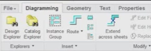
As you can see, the route fiber option is blue, so when the operator clicks on it it automatically generates a fiber without the catalog explorer opened, and if its placed, a dataset can be assigned to it later.
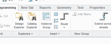
The second picture shows my ribbon, where the route fiber command is grey, so it opens the catalog explorer every time i click on it.
Although I don't really understand how record a trail works, but I think it wouldn't solve my problem like this.
You mentioned a video, but I cant see it, could you link it again? I'd like to try the record a trail option anyway.
Thank you!
Lac
Jun 22, 2015
10:46 AM
- Mark as New
- Bookmark
- Subscribe
- Mute
- Subscribe to RSS Feed
- Permalink
- Notify Moderator
Jun 22, 2015
10:46 AM
Lac
the video was posted in the following thread
I have just gone to the thread and the video plays without any issues
Please let me know if you still cannot see the video
