Turn on suggestions
Auto-suggest helps you quickly narrow down your search results by suggesting possible matches as you type.
Showing results for
Turn on suggestions
Auto-suggest helps you quickly narrow down your search results by suggesting possible matches as you type.
Showing results for
Community Tip - If community subscription notifications are filling up your inbox you can set up a daily digest and get all your notifications in a single email. X
- Community
- Creo+ and Creo Parametric
- 3D Part & Assembly Design
- Mechanism & Redundancies
Options
- Subscribe to RSS Feed
- Mark Topic as New
- Mark Topic as Read
- Float this Topic for Current User
- Bookmark
- Subscribe
- Mute
- Printer Friendly Page
Mechanism & Redundancies
Sep 13, 2015
05:57 PM
- Mark as New
- Bookmark
- Subscribe
- Mute
- Subscribe to RSS Feed
- Permalink
- Notify Moderator
Sep 13, 2015
05:57 PM
Mechanism & Redundancies
Hello,
I have two questions.
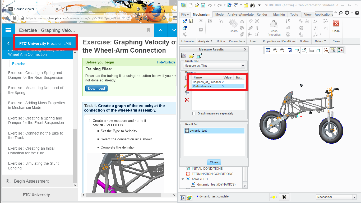
Is there a way to determine where is the redundancy while performing a mechanism analysis?
For example, let's say that you assemble a mechanism and check all the steps previous to the analysis (motion axis settings, dragging operations, reconnect etc.)
Now you run an analysis and when you measure the redundancies Boom! Your model has 6 redundancies!
So, in other words, what's your advice to find such redundancies? (Besides checking the connections one by one, or adding constraints in the analysis dialog box) Is there a way to find the exact connection that creates such redundancies?
The second question,
I know that redundancies are important because it ensures the quality of the analysis, but..
Is this absolutely true?
Thanks!
This thread is inactive and closed by the PTC Community Management Team. If you would like to provide a reply and re-open this thread, please notify the moderator and reference the thread. You may also use "Start a topic" button to ask a new question. Please be sure to include what version of the PTC product you are using so another community member knowledgeable about your version may be able to assist.
Solved! Go to Solution.
Labels:
- Labels:
-
General
1 ACCEPTED SOLUTION
Accepted Solutions
Sep 14, 2015
01:04 PM
- Mark as New
- Bookmark
- Subscribe
- Mute
- Subscribe to RSS Feed
- Permalink
- Notify Moderator
Sep 14, 2015
01:04 PM
Redundancies are a "System" measurement you can select to monitor. You will not know where the redundant DOF is, but at least you'll know to look. You can run your mechanism one link/member at a time to see where the redundancy is added. Redundancies in an analysis can be bad if you need to resolve accurate loads at each joint and two (or more) are redundant - the solver may not split them properly. The total loading should be accurate, but it may not calculate how the load is divided between the two.
3 REPLIES 3
Sep 14, 2015
01:04 PM
- Mark as New
- Bookmark
- Subscribe
- Mute
- Subscribe to RSS Feed
- Permalink
- Notify Moderator
Sep 14, 2015
01:04 PM
Redundancies are a "System" measurement you can select to monitor. You will not know where the redundant DOF is, but at least you'll know to look. You can run your mechanism one link/member at a time to see where the redundancy is added. Redundancies in an analysis can be bad if you need to resolve accurate loads at each joint and two (or more) are redundant - the solver may not split them properly. The total loading should be accurate, but it may not calculate how the load is divided between the two.
Sep 15, 2015
03:13 PM
- Mark as New
- Bookmark
- Subscribe
- Mute
- Subscribe to RSS Feed
- Permalink
- Notify Moderator
Sep 15, 2015
03:13 PM
Yes and No.
This is the important thing "The total loading should be accurate, but it may not calculate how the load is divided between the two." You are right. I solved the problem thanks to you, but it wasn't an assembly-connection problem.
The thing is that while assembling, I decide to put the final part as an "eraser part", I haven't modeled correctly that part yet, it was like a basic representation of the real part, so it causes a huge collision in the assembly. That huge collision, causes that the system wasn't able to "calculate how the load is divided between the two.". I did run my mechanism one member at time, and yes, that was the result.
In conclusion, be aware of huge collisions, it causes redundancies.
Sep 15, 2015
07:44 PM
- Mark as New
- Bookmark
- Subscribe
- Mute
- Subscribe to RSS Feed
- Permalink
- Notify Moderator
Sep 15, 2015
07:44 PM
Look what I just found
So now, I have more questions than ever