
Turn on suggestions
Auto-suggest helps you quickly narrow down your search results by suggesting possible matches as you type.
Showing results for
Turn on suggestions
Auto-suggest helps you quickly narrow down your search results by suggesting possible matches as you type.
Showing results for
Community Tip - You can Bookmark boards, posts or articles that you'd like to access again easily! X
- Community
- Creo+ and Creo Parametric
- 3D Part & Assembly Design
- Simulate - finding average strain on a surface (st...
Options
- Subscribe to RSS Feed
- Mark Topic as New
- Mark Topic as Read
- Float this Topic for Current User
- Bookmark
- Subscribe
- Mute
- Printer Friendly Page
Simulate - finding average strain on a surface (strain gauge simulation)
Sep 22, 2015
06:26 PM
- Mark as New
- Bookmark
- Subscribe
- Mute
- Subscribe to RSS Feed
- Permalink
- Notify Moderator
Sep 22, 2015
06:26 PM
Simulate - finding average strain on a surface (strain gauge simulation)
I am trying to determine the average strain over a defined area, in a specific direction. The goal is to simulate the reading of a strain gauge that is bonded to my part. I can measure the min/max strain on the surface. I can also measure the strain at a point. The best I've been able to do is create a pattern of points on my surface, measure the strain at each point, then create a computed measure to average the measured strain values.
Anyone have a better/cleaner way?
Labels:
- Labels:
-
Surfacing
10 REPLIES 10
Sep 23, 2015
04:26 AM
- Mark as New
- Bookmark
- Subscribe
- Mute
- Subscribe to RSS Feed
- Permalink
- Notify Moderator
Sep 23, 2015
04:26 AM
I don't think there's any better/easier way than what you are doing. Does the strain vary considerably within the area of the gague? Perhaps 2 points is sufficient..? Or maybe measuring the value at the center of the gague location, is good enough?
An alternative could be to measure the displacement at two locations: d1 at position x1, and d2 at pos x2. Then calculate the average strain as (norm(x1+d1)-norm(x2+d2)) /norm(x1-x2). (I.e. change in distance divided by original distance between the points. This would then be the strain in the direction of the line between the points x1 and x2.
x1,x2,d1 and d2 are 3x1 vectors.
/Mats L
Sep 23, 2015
04:37 AM
- Mark as New
- Bookmark
- Subscribe
- Mute
- Subscribe to RSS Feed
- Permalink
- Notify Moderator
Sep 23, 2015
04:37 AM
If the strain varies considerably within the area of one strain gauge, then you should reconsider the location of the strain gauge (or maybe even reconsider the use of strain gauges)!
Sep 23, 2015
05:50 AM
- Mark as New
- Bookmark
- Subscribe
- Mute
- Subscribe to RSS Feed
- Permalink
- Notify Moderator
Sep 23, 2015
05:50 AM
Good point... put strain gagues where the stress/strain gradient is low, verify that FEA matches those measurements, then you can probably trust FEA in more critical locations/locations with high stress and/or high stress gradient, where FEA and/or measurements, might be less accurate.
If the purpose of the strain gague measurement is to find out the forces acting on a structure, then it's always a good strategy to put gagues in non-critical locations with low gradients, preferably far away from constraints etc. that might be a source of error in the FEA model. This is more accurate.
A funnny anecdote, having struggled with evaluating strain gague measurement, I learned that the expression "Murphy's law", meaning "if anything can go wrong, then it will" comes from someone doing strain gague measurements... 
Sep 23, 2015
11:54 AM
- Mark as New
- Bookmark
- Subscribe
- Mute
- Subscribe to RSS Feed
- Permalink
- Notify Moderator
Sep 23, 2015
11:54 AM
Thanks for the feedback. The strain gauge location is already set (not by me). The gradient is not huge, but it is there. So far I've just been looking at dummy (simplified) load cases, next I will plug in some real world loads and see what the gradient looks like. I've been looking only at existing product to compare to empirical data. If I can come up with a clean way to do the analysis digitally, then we will use it on future projects.
I found the min and max over the bonded area and averaged them. There was about a 4.5% difference between that number and the average of the strain values of a 17 point pattern on the surface. Considering that we target +/- 1% for the final reading accuracy, that is a large number.
Sep 29, 2015
06:02 AM
- Mark as New
- Bookmark
- Subscribe
- Mute
- Subscribe to RSS Feed
- Permalink
- Notify Moderator
Sep 29, 2015
06:02 AM
Hi,
We created a small 'array' of points for a gauge and at each point created directional strain measures.
The rest was done in a spreadsheet.
For a small gauge length, the results from a single point were close enough which reduced the number of numbers requiring manipulation.
Computed measures were ok but difficult to maintain. Spreadsheets easily enable one to expand the calculation.
I would be interested to know how far apart your model and practical measurements are. There are so many sources of error: actual gauge positioning, Bauschinger's effect, adhesive, real versus model geometry, real versus model loads and constraints ... an accuracy of 1% seems quite optimistic.
Sep 29, 2015
08:22 AM
- Mark as New
- Bookmark
- Subscribe
- Mute
- Subscribe to RSS Feed
- Permalink
- Notify Moderator
Sep 29, 2015
08:22 AM
I used to work with evaluating strain gague measurements. Heavy machine with rotating load. One load vector component was supported by hydraulics, thus the force magnitude (but not direction) could easily be measured. When I started this work, the measurements were done "by them selves" so to speak, the comparison with FEA results could not be done because of insufficient technique/method to evaluate load direction. Rainflow count etc was done directly on measured signals. I felt this was unsatisfactory, so I developed a technique to find the load direction vs time. As result I could compare FEA results (calculated with load from measured hydraulic pressure), with strain gague measurements. For some gagues, the correlation was quite good, perhaps 2% deviation. For other gagues up to maybe 10% deviation between measurement and FEA was observed. If the calculated stress is to be used for fatigue life evalulation using an S-N curve, then a 10% error will produce a massive error in calculated fatigue life, especially in high cycle fatigue. In my case, I think the main reasons for the deviation, were some conservative assumptions regarding the location for load application and that the constraints were assumed to be moment free, which is not entirely correct. I didn't stay long enough at that company to refine the FE-model to improve these results. Instead I settled for developing a technique that was "good enough" for comparisons. I basically adjusted the SN curve to compensate for errors in the stress calculation, in order to obtain the "correct" expected fatigue life for a "normal" or "average" load spectrum" and then I used this for comparisons, "what if studies" etc. So eventhough the method is uncertain, I was able to answer some questions that until then had been unanswered. Long story short: +/-1% is very optimistic I would say.
Sep 29, 2015
11:17 AM
- Mark as New
- Bookmark
- Subscribe
- Mute
- Subscribe to RSS Feed
- Permalink
- Notify Moderator
Sep 29, 2015
11:17 AM
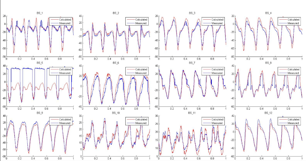
I found some pics from the project mentioned above. It's a series of gagues in various locations around the machine. It's measured stress vs stress calculated in FEA using measured hydraulic pressure. Some gagues show a quite good, others not so good correlation betwen measurement and FEA. Its a machine with a load that rotates at fixed speed, but the load magnitude varies cyclically but eratically with the same frequency as the rotation. One of them is erroneous I Think, "BS5". In most cases, the calculated stress is higher than the measured one, due to some conservative assumptions in the load application in the FE-model.
Sep 29, 2015
10:39 AM
- Mark as New
- Bookmark
- Subscribe
- Mute
- Subscribe to RSS Feed
- Permalink
- Notify Moderator
Sep 29, 2015
10:39 AM
Normally your model convergence is only what, up to 5%? so that is already 5% that you can be "off" from the strain gauge measurements. And then there is all these other influences you mentioned.
I'd be happy with 10% in "easy" locations (as long as the trend agrees with the FEA  )
)
In difficult locations (multi-axial stress, near contacts, ...) I would not even worry too much about 15-20% difference.
I'm interested to see what other people use as criteria...
Sep 29, 2015
11:39 AM
- Mark as New
- Bookmark
- Subscribe
- Mute
- Subscribe to RSS Feed
- Permalink
- Notify Moderator
Sep 29, 2015
11:39 AM
We rarely get the opportunity to 'close the loop'
On the occasions we do,
Model the way the object will be tested and not the way it will be used
Choose locations away from high gradients
Align gauge with the modelled max P stress
Choose locations where the large part the gauge range can be used to improve resolution without overstraining it/adhesive
Gauges cycled to settle into a steady hysteresis loop.
Steel castings ... 20%+
Nice lab specimens - 5%
... steel castings, the real thing is nothing like the CAD model to start with.
Sep 29, 2015
11:56 AM
- Mark as New
- Bookmark
- Subscribe
- Mute
- Subscribe to RSS Feed
- Permalink
- Notify Moderator
Sep 29, 2015
11:56 AM
Thanks all. I should clarify - the target accuracy of the finished product is +/- 1%. The finished part is calibrated and can already achieve this accuracy. I was referring more to the simplified load case I was using to collect some initial data and the fact that the resulting strain gradient was higher than I expected. I haven't been able to get back on this project yet to put in a real-world load case to see what the strain gradient looks like.
For the analysis, I don't need to correlate the FEA strain to the real-world strain with any accuracy. As long as the model stays consistent to itself, that will be sufficient for me to get what I need. Basically, I am looking for the best way to simulate the strain gauge reading.
Sounds like you guys have a LOT more experience with strain gauges that I do. I haven't played around with them since I was in school and we built our own load cell, but that was more than a few years ago (and it was all hand-calcs, no FEA)...
