
Turn on suggestions
Auto-suggest helps you quickly narrow down your search results by suggesting possible matches as you type.
Showing results for
Turn on suggestions
Auto-suggest helps you quickly narrow down your search results by suggesting possible matches as you type.
Showing results for
Community Tip - New to the community? Learn how to post a question and get help from PTC and industry experts! X
- Community
- Creo+ and Creo Parametric
- 3D Part & Assembly Design
- Remove interference material as a result of mechan...
Options
- Subscribe to RSS Feed
- Mark Topic as New
- Mark Topic as Read
- Float this Topic for Current User
- Bookmark
- Subscribe
- Mute
- Printer Friendly Page
Remove interference material as a result of mechansim
Nov 03, 2015
11:29 AM
- Mark as New
- Bookmark
- Subscribe
- Mute
- Subscribe to RSS Feed
- Permalink
- Notify Moderator
Nov 03, 2015
11:29 AM
Remove interference material as a result of mechansim
I am running a mechanism of essentially a gear shape. I would like to male tooth to cut out the female section as a result of the motion I have defined.
These aren't really gears but a special profile and would like to analyze what the female side should be so nothing interferes while they are rolling. Reminder that both parts are moving..
Thanks!
Steve
This thread is inactive and closed by the PTC Community Management Team. If you would like to provide a reply and re-open this thread, please notify the moderator and reference the thread. You may also use "Start a topic" button to ask a new question. Please be sure to include what version of the PTC product you are using so another community member knowledgeable about your version may be able to assist.
Labels:
- Labels:
-
General
5 REPLIES 5
Nov 04, 2015
06:34 AM
- Mark as New
- Bookmark
- Subscribe
- Mute
- Subscribe to RSS Feed
- Permalink
- Notify Moderator
Nov 04, 2015
06:34 AM
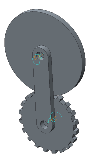
I have never tried this, but I suspect it is possible to create a "motion envelope" of the new gear geometry. The "problem" in this case, is that the motion envelope is fixed relative to ground. So you will have to define the motion of your parts so that one of them, "female" is fixed to ground, and the other one has its motion defined relative to the fixed part. (*testing*). It turns out the resulting geometry (I would think), is too coarse, see below. Note that the resulting "toothed" surface is the negative of the desired gear wheel.
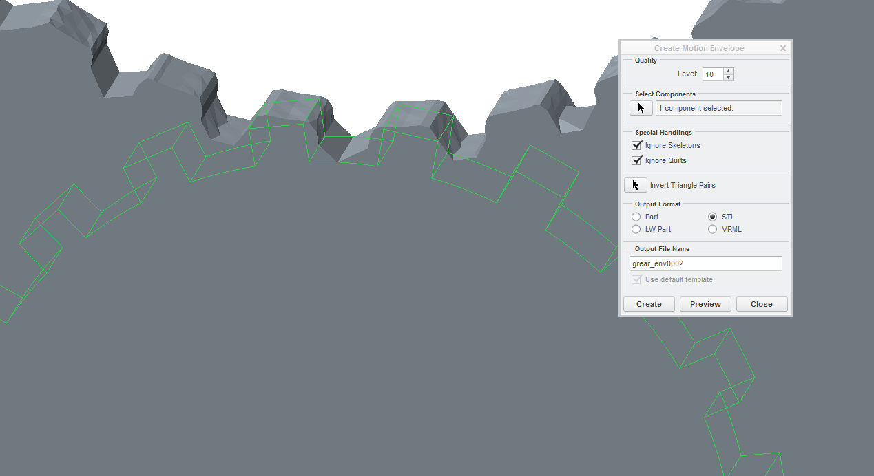
Motion model used:
Nov 04, 2015
06:45 AM
- Mark as New
- Bookmark
- Subscribe
- Mute
- Subscribe to RSS Feed
- Permalink
- Notify Moderator
Nov 04, 2015
06:45 AM
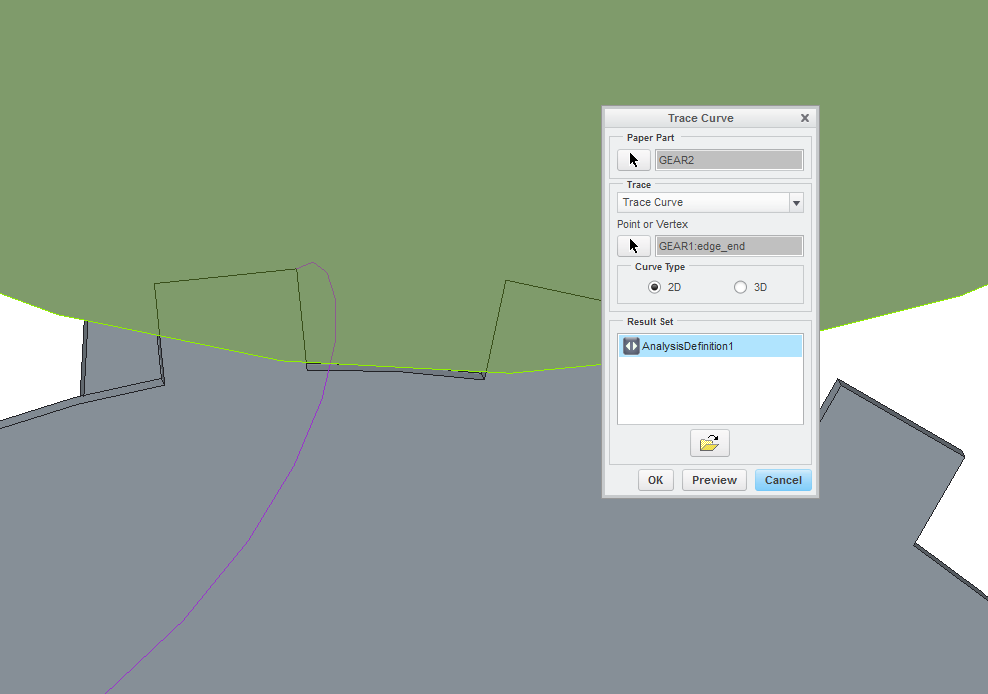
Next attempt would be to create a "trace curve" from the "male" onto the "female" paper part. In this case you can prescribe motions to the parts as you wish. This only creates the profile of a single gear tooth profile. I guess you might need to create several trace curves to get an accurate femate tooth geometry. Material on the "inside"of the trace curve(s) should be removed. It might be necessary to generate several trace curves, for a series of datum points along the "male's" gear surface.
Nov 04, 2015
06:59 AM
- Mark as New
- Bookmark
- Subscribe
- Mute
- Subscribe to RSS Feed
- Permalink
- Notify Moderator
Nov 04, 2015
06:59 AM
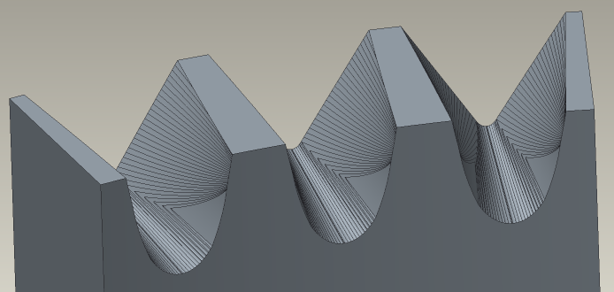
I've done this not using Mechanism, but by creating a surface of the 'male' tooth and then patterning it at very small increments. The increment size was limited by accuracy / regen issues so the result was a bit facetted, but we actually milled parts (face gears) from the model and they inspected OK and seemed to work fine (in a lightly-loaded actuation application though, not 'proper' power transmission).
Nov 11, 2015
03:31 PM
- Mark as New
- Bookmark
- Subscribe
- Mute
- Subscribe to RSS Feed
- Permalink
- Notify Moderator
Nov 11, 2015
03:31 PM
So I was able get my result by using the trace curve method to check about 60 points and then run a spline though the tangent of each of them. I want to try your method, but I can't get around the fact that while I can pattern the male, I would have to move the female at the same time in order to get the correct profile...
can you clarify?
Dec 10, 2015
07:18 AM
- Mark as New
- Bookmark
- Subscribe
- Mute
- Subscribe to RSS Feed
- Permalink
- Notify Moderator
Dec 10, 2015
07:18 AM
Sorry Steve, for some reason I hadn't seen your reply until now!
Basically I constructed datums for the cutter using relations, so that the cutter both rotated about its own axis and also 'orbited' about the axis of the part. In your case for parallel-axis gears, you'd need to pattern the centre of your 'cutter' gear along an arc (I'd probably start by patterning a datum plane through the axis of the 'part' gear, which then positions the axis of the 'cutter') but then create a reference to define the angle of the 'cutter' using a relation based on the centre position.
Imagine your 'cutter' rolling around the 'part', while the 'part' remains stationary.
