
Turn on suggestions
Auto-suggest helps you quickly narrow down your search results by suggesting possible matches as you type.
Showing results for
Turn on suggestions
Auto-suggest helps you quickly narrow down your search results by suggesting possible matches as you type.
Showing results for
Community Tip - You can change your system assigned username to something more personal in your community settings. X
- Community
- Creo+ and Creo Parametric
- 3D Part & Assembly Design
- How to constrain long profile?
Options
- Subscribe to RSS Feed
- Mark Topic as New
- Mark Topic as Read
- Float this Topic for Current User
- Bookmark
- Subscribe
- Mute
- Printer Friendly Page
How to constrain long profile?
Jan 14, 2016
06:13 AM
- Mark as New
- Bookmark
- Subscribe
- Mute
- Subscribe to RSS Feed
- Permalink
- Notify Moderator
Jan 14, 2016
06:13 AM
How to constrain long profile?
Hello,
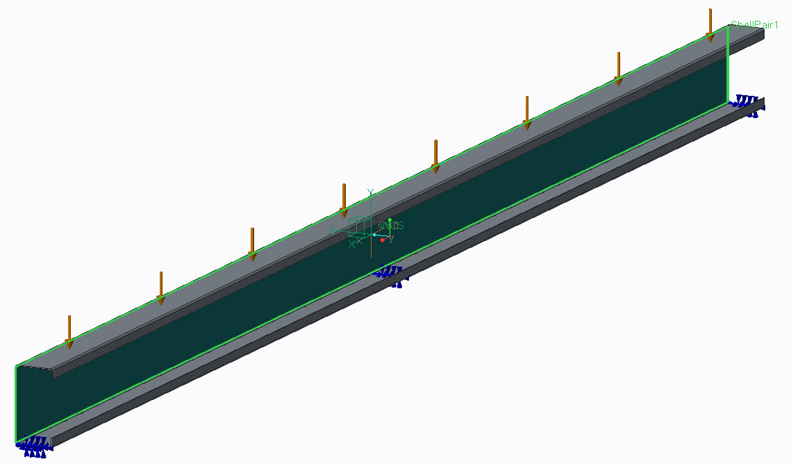
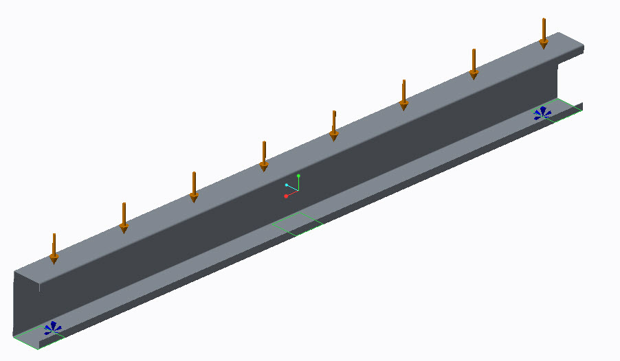
What is the best practise to create constraints for a profile? The thickness is 1-3mm and length 1000 to 6000. I am using family table and want to make sensitivity study.
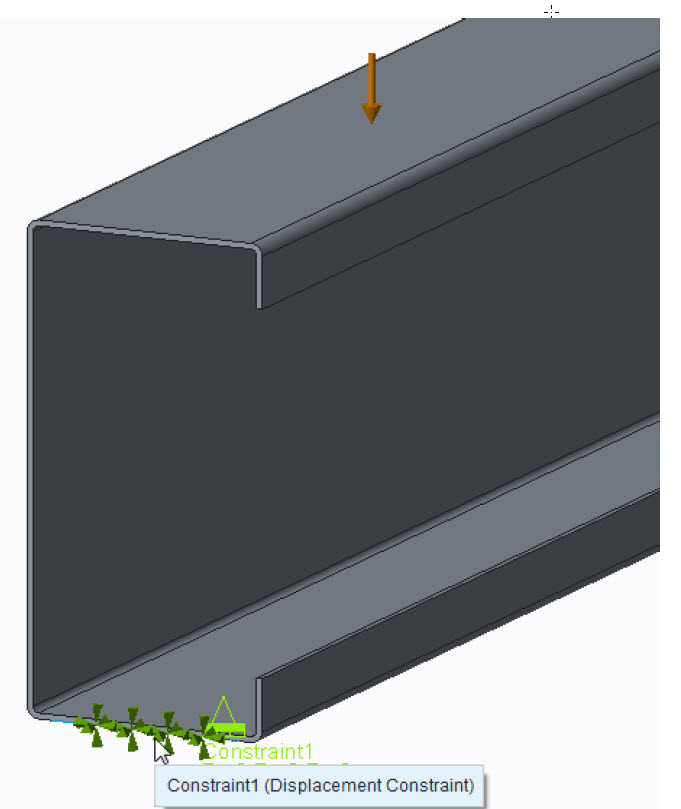
I am using shell pairs and I create surface regions as constraints. This causes singularities to the edge of the regions and
the result stress von Mises is unreal.
Jouni Ahola
Labels:
- Labels:
-
Surfacing
10 REPLIES 10
Jan 14, 2016
07:06 AM
- Mark as New
- Bookmark
- Subscribe
- Mute
- Subscribe to RSS Feed
- Permalink
- Notify Moderator
Jan 14, 2016
07:06 AM
There are different techniques.
1. Extend your model to also include what the profile is attached to. This might involve contacts (which need to be modeled with solid elements in Creo). Whatever it is your profile is attached to, this is elastic and can deform, which reduces stress peaks at the edge of your constrained surfaces.
2. Ignore the stress peaks at the edge of your constrained surfaces. The critical stress can be evaluated using for example the hot spot method, which extrapolates the stress from the "interior" to the edge where your non-linear stress peak is located. For example the IIW has documentation on how to use the "Hot spot method"
3. Use a beam combined with a weighted link, that connects a beam endpoint to your constrained surface. The weighted link allows some deformation of the target surface and you will get more smooth results.
In eihter case, you can still use for example the hotspot method to evaluate the stress level. This is OK according to some norms, I think also the Eurocode 3 standard allows evaluating welds according to the "hotspot method".
Here's a demo I did some years ago, on weighted links (in Swedish)... Mechanica - YouTube
/Mats L
Jan 14, 2016
10:51 AM
- Mark as New
- Bookmark
- Subscribe
- Mute
- Subscribe to RSS Feed
- Permalink
- Notify Moderator
Jan 14, 2016
10:51 AM
Thank you for the answer. I made as in your first answer. Now it looks better. I made an assembly, I will attach picture later. I need to test rigid links as well.
I can not ignore peaks, because I need Excel graphs for different height and length of the profiles. I am going to make sensitivity study
and profile lenght is varying from 1000 to 6000mm. And even 12 000mm profile lengths.
Beam is one what I need to consider.
I noticed one rather strange thing. When I change the profile length from 1000-5999mm, I can use shell for meshing. But when the length is 6000 or more, Creo automatically use solid surfaces for meshing???
Jan 29, 2016
06:52 AM
- Mark as New
- Bookmark
- Subscribe
- Mute
- Subscribe to RSS Feed
- Permalink
- Notify Moderator
Jan 29, 2016
06:52 AM
How about just using beam elements for your sensitivity study?
- you can export graphs directly to MS Excel
- Much faster to run
- Usually enough information for "standard beam bending"
The beam length is not something that drives element types. Please check your shell definition with review model.
Jan 29, 2016
08:24 AM
- Mark as New
- Bookmark
- Subscribe
- Mute
- Subscribe to RSS Feed
- Permalink
- Notify Moderator
Jan 29, 2016
08:24 AM
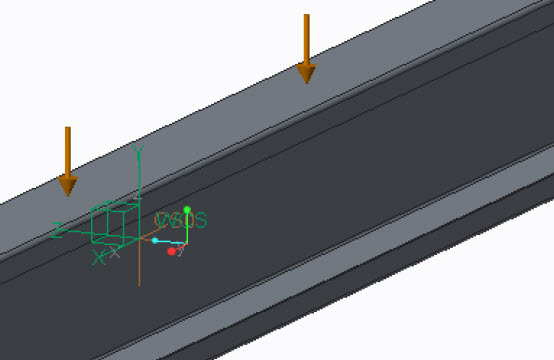
In many cases beam elements are useful, as you say, only a few elements can replace many shell/solid elements. But in this case I would stay with shell elements. It's an open section, and beam elements are not good at capturing torsion, unless it is a circular cross section. In this case, it seems the load is uniform, and I see it as unlikely that the load resultant acts in the line of the shear center of the beam section. I.e. there will be torsion of the beam.
Jan 30, 2016
06:39 PM
- Mark as New
- Bookmark
- Subscribe
- Mute
- Subscribe to RSS Feed
- Permalink
- Notify Moderator
Jan 30, 2016
06:39 PM
Now I change absolute accuracy and shell elements can be made as long profile as I want. So, the length of the profile or shell elements is not the problem. Still I am not sure what is the best constraint method. I tried edge constraint and the result is better.
Some says that I should use hard curve, but I did not notice any differencies. I am not sure what is the meaning of the hard curve, -point or -surface.
And should I fix all translations and rotations or use different coordinate system (cylindrical)?
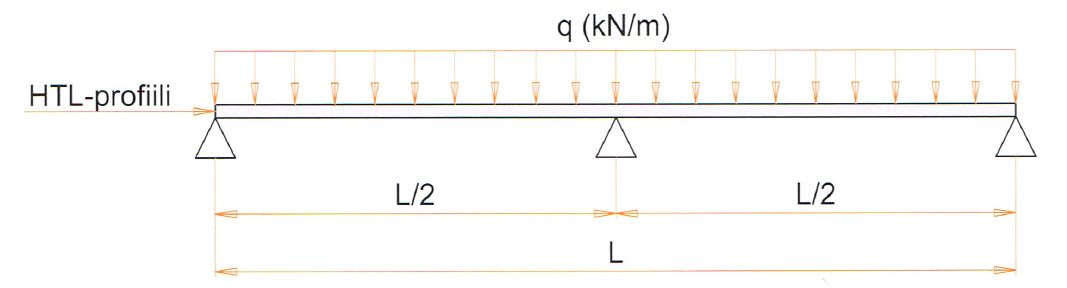
There are two different type of supports, 2-support and 3- support (in the middle) when the length is over 6000mm.
Feb 01, 2016
04:52 AM
- Mark as New
- Bookmark
- Subscribe
- Mute
- Subscribe to RSS Feed
- Permalink
- Notify Moderator
Feb 01, 2016
04:52 AM
Hard Objects in Creo Simulate:
- point
- curve
- surface
One has datum points, datum curves and surfaces (quilts) in Creo Parametric. Some of them are used to generate mesh with Creo Simulate Out Of The Box settings. How ever, it can happen, that some (as an example) datum curves will not come as element edges - if you want to be sure, that curve will be part of element edges - assign Hard Curve controller to curve.
One can get "insufficiently constrained" error => Fatal Error since some of joints are failing (some connections are made to datum features not existing at mesh). Therefore sometimes it is mandatory to use Hard Objects to establish connectivity as well.
And at last yes, the elements created with this "hard" option have still ability to deform as per their material and geometrical properties.
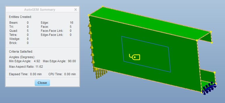
Mesh as default
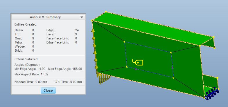
Mesh with Hard Curve on sketched entity
As you notice, the shell mesher of Creo Simulate is quite aggressive. Therefore it might be wise to use other mesh controllers as well. In following Hard Curve and Edge Distribution is used. Bear in mind however, that this is p-element mesh, not h-element, with automatic convergence (SPA, MPA solution algorithms), when looking at mesh quality etc.
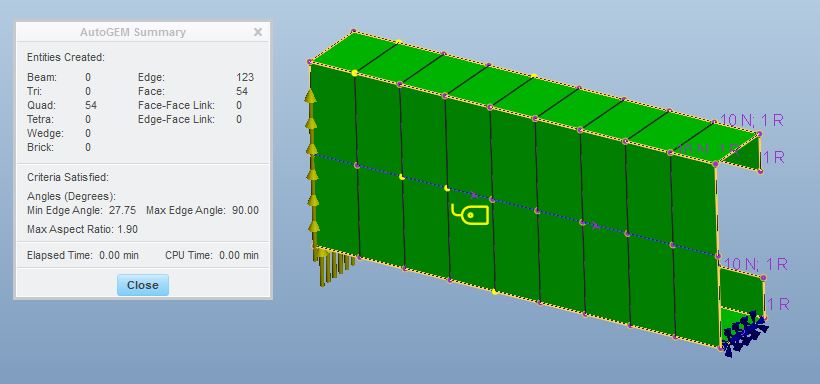
Only Shell Quad Elements
Then you might want to consider the possibility of thin solids in this case.
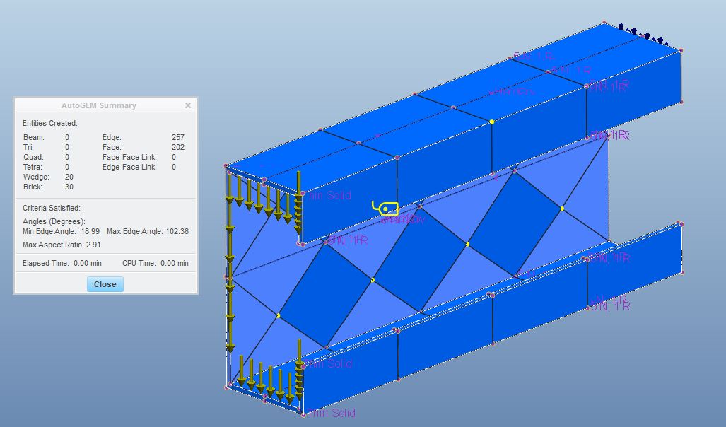
Sample beam meshed with Solid Brick and Wedge elements. NO tetra elements.
###
Regarding your question on fixing rotations, please consider the constrains (the real support) ability to carry moments, i.e. Forces and Moments should have zero resultant. Home>Loads > Review Total Load functionality might be helpful.
Feb 01, 2016
09:58 AM
- Mark as New
- Bookmark
- Subscribe
- Mute
- Subscribe to RSS Feed
- Permalink
- Notify Moderator
Feb 01, 2016
09:58 AM
Thank you, it helped more about hard curves etc.
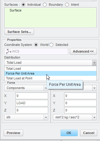
I am still wondering what is the best way to use static load (kN/m)? Should I use Force Per Unit Area distribution and how to calculate it? Now I have created parameter LOAD. I am using Total load, but I think it should be Force Per Unit Area distribution.
And the other question is allowed deflection, it is Profile Length divided by 200 (L/200) I have parameter PL for profile length. Can I make Measure Definition or relation or something for L/200?
Feb 02, 2016
02:09 AM
- Mark as New
- Bookmark
- Subscribe
- Mute
- Subscribe to RSS Feed
- Permalink
- Notify Moderator
Feb 02, 2016
02:09 AM
For allowed relative deflection, you may use computed measure.
- create parameter in Creo Parametric witch will have value of length of your beam (use relations)
- length=d8
- create measure in Creo Simulate for Driven parameter
- length_parameter
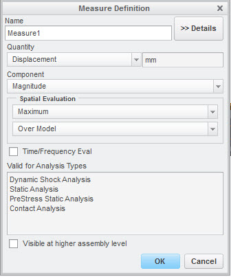
- create max_disp_mang_user measure in Creo Simulate
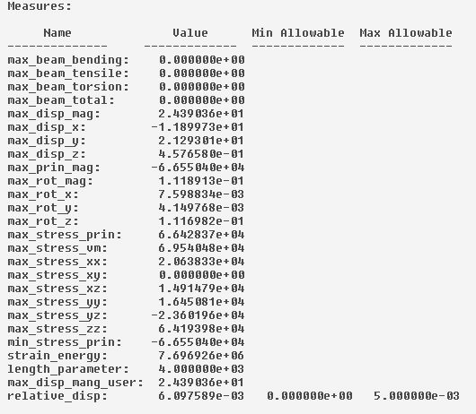
- create computed measure relative_disp in Creo Simulate
- max_disp_mang_user/length_parameter
- you may Specify Allowables (0, 0.005), which will show on log
###
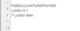
Your loading height q has units of [N/mm]. If the length of beam will increase, so will the total force F=ql. This will lead to possibility to use another relation to capture the required force F for certain q (total load case). Or use your imagination&calculator to get proper value for Force per unit area and use that as is.
You can use Creo Parametric parameters at Creo Simulate force dialog. Click RMB (Rigth Mouse Button) at force component definition, pick Parameter..
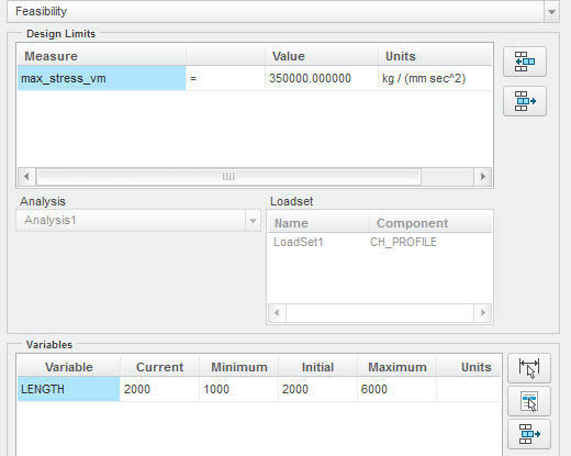
You can use feasibility/optimization to find what is the max allowable length for beam, when:
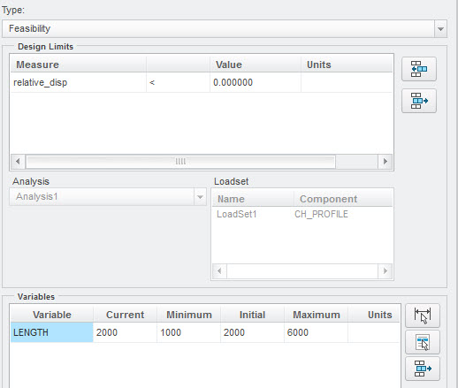
- relative deflection must be < 1/200
- stress must be less < max allovable
- etc...
Feb 02, 2016
07:39 AM
- Mark as New
- Bookmark
- Subscribe
- Mute
- Subscribe to RSS Feed
- Permalink
- Notify Moderator
Feb 02, 2016
07:39 AM
I made relations and parameters for the load and I think it works now.
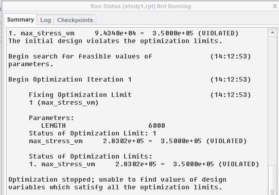
And the feasibility works as well. At least I can check the maximum length for profiles .
The relative deflection is not defined yet.. I do not know how to create limits 1/200 for the profile. Is it relation also?
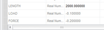
I have created those parameters below:
- create parameter in Creo Parametric witch will have value of length of your beam (use relations)
- length=d8
- create measure in Creo Simulate for Driven parameter
- length_parameter
- create max_disp_mang_user measure in Creo Simulate
- create computed measure relative_disp in Creo Simulate
- max_disp_mang_user/length_parameter
- you may Specify Allowables (0, 0.005), which will show on log
Feb 02, 2016
07:55 AM
- Mark as New
- Bookmark
- Subscribe
- Mute
- Subscribe to RSS Feed
- Permalink
- Notify Moderator
Feb 02, 2016
07:55 AM
Make simple model and verify your relations actually work on that, before starting to do a full blown series of advanced stuff..
You can have multiple design limits:
- stress <350 MPa
- relative displacement <0.005
Please note, that relation length=d8, must be based on your model (d8 was OK for mine). It seems that your feasibility study is not finding a solution...
More knowledge can be found at: Introduction to Creo Simulate - PDSVision
