
Turn on suggestions
Auto-suggest helps you quickly narrow down your search results by suggesting possible matches as you type.
Showing results for
Turn on suggestions
Auto-suggest helps you quickly narrow down your search results by suggesting possible matches as you type.
Showing results for
Community Tip - Have a PTC product question you need answered fast? Chances are someone has asked it before. Learn about the community search. X
- Community
- Creo+ and Creo Parametric
- Manufacturing (CAM)
- Right angle head?
Options
- Subscribe to RSS Feed
- Mark Topic as New
- Mark Topic as Read
- Float this Topic for Current User
- Bookmark
- Subscribe
- Mute
- Printer Friendly Page
Right angle head?
Mar 02, 2016
10:32 AM
- Mark as New
- Bookmark
- Subscribe
- Mute
- Subscribe to RSS Feed
- Permalink
- Notify Moderator
Mar 02, 2016
10:32 AM
Right angle head?
Anyone familiar with writing toolpath for right angle head? Do I build a special tool?Create a coordinate system that makes the code come out right, or what?
This thread is inactive and closed by the PTC Community Management Team. If you would like to provide a reply and re-open this thread, please notify the moderator and reference the thread. You may also use "Start a topic" button to ask a new question. Please be sure to include what version of the PTC product you are using so another community member knowledgeable about your version may be able to assist.
Labels:
- Labels:
-
General
6 REPLIES 6
Mar 03, 2016
03:34 AM
- Mark as New
- Bookmark
- Subscribe
- Mute
- Subscribe to RSS Feed
- Permalink
- Notify Moderator
Mar 03, 2016
03:34 AM
I don't know but I'm very interested by this topic. 
Mar 03, 2016
07:08 AM
- Mark as New
- Bookmark
- Subscribe
- Mute
- Subscribe to RSS Feed
- Permalink
- Notify Moderator
Mar 03, 2016
07:08 AM
I haven't had the joy of doing this, but my method would be:
(1) Assuming it's 3-axis milling, Creo seems to always work with the Z-axis as the tool axis.
(2) Given that, start by defining the coordinate system oriented as if I wasn't working with a 90-degree head.
(3) Program all sequences with this coordinate system.
(4) To output the program, use a transformation (rotate) to get the output in the orientation needed. For example, rotate 90 degrees about the Y-axis. You've got to be very careful about angle conventions and directions, but doing a simple test will help you to get it right. You need to check the "Compute CL" box before outputting the file to get it to apply the rotation.
I just tried this out on a simple program and it seems to work. The only "bad" thing I see is that I can't do a material removal simulation on the transformed program.
Mar 03, 2016
07:10 AM
- Mark as New
- Bookmark
- Subscribe
- Mute
- Subscribe to RSS Feed
- Permalink
- Notify Moderator
Mar 03, 2016
07:10 AM
Oh, yeah, one other thing I just thought of. Make sure you don't post-process the program with any tool change calls in it. I'd imagine a 90 degree head would not like being rammed into the tool change carousel. I get the shudders thinking about it.
Mar 03, 2016
07:36 AM
- Mark as New
- Bookmark
- Subscribe
- Mute
- Subscribe to RSS Feed
- Permalink
- Notify Moderator
Mar 03, 2016
07:36 AM
Unfortunately I am posting this to a 4 axis horizontal mill and I need to get the correct Baxis output if possible. Oh and this is a coolant driven right angle head that will store in your tool rack. Nice tool! Go to eltool.com and check it out
Mar 03, 2016
08:29 AM
- Mark as New
- Bookmark
- Subscribe
- Mute
- Subscribe to RSS Feed
- Permalink
- Notify Moderator
Mar 03, 2016
08:29 AM
I would also need a G19 output in the code to enable using cutter comp
Mar 08, 2016
02:55 PM
- Mark as New
- Bookmark
- Subscribe
- Mute
- Subscribe to RSS Feed
- Permalink
- Notify Moderator
Mar 08, 2016
02:55 PM
Bobby,
The following information is copied from the NC Manufacturing help file:
"Automatic Tool Attachment
Tool attachment is an assembly of a tool and an attachment. The tool and the attachment can be part models or subassemblies.
When a tool attachment is used in an NC sequence, you can use the TOOL_ATTCHMENT parameter for NC Manufacturing to identify the attachment from the tool attachment assembly. You can specify the TOOL_ATTCHMENT parameter while defining or modifying a part or subassembly. The possible values for the TOOL_ATTCHMENT parameter are YES and NO. For the attachment part or assembly the value must be set to YES.
While defining an NC sequence, NC Manufacturing identifies the attachment part or assembly by the value of the TOOL_ATTCHMENT parameter. This part or assembly is then automatically used as the attachment for the NC sequence.
TOOLING LIBRARY Catalog
To Create a Tool Attachment
Create a new Pro/ENGINEER model of type Part or Assembly. Assign the name of the attachment to this part or assembly. Reproduce the geometry of the attachment by using the appropriate construction features (protrusions, cuts, and so on). This geometric representation can be as accurate or as simplified as you wish.
Create a coordinate system to define the holder orientation on the machine, and change the name of the coordinate system to SPINDLE_CONTROL_POINT. When you use the attachment, the z-axis of the SPINDLE_CONTROL_POINT coordinate system is aligned with the z-axis of the Machine coordinate system.
Create a second coordinate system, which provides the tool orientation and is used to attach the tool. Change the name of the coordinate system to TOOL_ATTACH_POINT. When you use the attachment, the z-axis of the TOOL_ATTACH_POINT coordinate system is aligned with the z-axis of the NC sequence coordinate system. If you use a solid tool model, you must define an additional coordinate system named ATTACHMENT in the tool model, and NC Manufacturing attaches the tool by aligning this coordinate system with the TOOL_ATTACH_POINT coordinate system of the attachment. If the ATTACHMENT coordinate system is not defined in a solid tool, NC Manufacturing uses the TIP coordinate system in its place. If you use a parameter-driven tool, NC Manufacturing attaches the top end of the tool to the TOOL_ATTACH_POINT coordinate system.
Add to the model a parameter with the name ATTACHMENT_NUMBER, type Integer, and value corresponding to the holder identification number. This value is used for CL output.
Save the model."
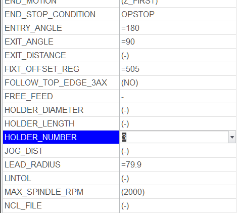
Note that you must specify the attachment number in the machining sequence, either by relation like so: "HOLDER_NUMBER = 3" or directly in the parameters page (see attachment).
If you create a solid model of the attachment, it can be displayed during 'PLAY PATH' by specifying the model name in Setup 'Attachment', or in the Options | Cutting Tool Adapter dialog of the collector.
Remove the attachment model before posting; it creates CL file entities that your post may not handle.
Lastly, you must have a post-processor that's set up to handle the attachment(s), otherwise, you'll get 'funny' output.
Ray Aviles
Announcements
Top Tags
