
Turn on suggestions
Auto-suggest helps you quickly narrow down your search results by suggesting possible matches as you type.
Showing results for
Turn on suggestions
Auto-suggest helps you quickly narrow down your search results by suggesting possible matches as you type.
Showing results for
Community Tip - You can subscribe to a forum, label or individual post and receive email notifications when someone posts a new topic or reply. Learn more! X
- Community
- Creo+ and Creo Parametric
- 3D Part & Assembly Design
- Piping branch connection
Options
- Subscribe to RSS Feed
- Mark Topic as New
- Mark Topic as Read
- Float this Topic for Current User
- Bookmark
- Subscribe
- Mute
- Printer Friendly Page
Piping branch connection
Jul 28, 2016
01:55 AM
- Mark as New
- Bookmark
- Subscribe
- Mute
- Subscribe to RSS Feed
- Permalink
- Notify Moderator
Jul 28, 2016
01:55 AM
Piping branch connection
I finished piping root shown below.

Please advice how to solve this problem
Labels:
- Labels:
-
Routed Syst. Design
11 REPLIES 11
Aug 01, 2016
08:49 AM
- Mark as New
- Bookmark
- Subscribe
- Mute
- Subscribe to RSS Feed
- Permalink
- Notify Moderator
Aug 01, 2016
08:49 AM
Hi you should probably look at how these would be manufactured. I doubt that a hole will be drilled in the side to create a branch and the end of the pipe scalloped out. It's far more likely that there will be branch tee fittings and clean normal cuts on the pipework. You should model up branch tees and add ports to allow them to be aligned properly.
Oct 19, 2016
11:42 AM
- Mark as New
- Bookmark
- Subscribe
- Mute
- Subscribe to RSS Feed
- Permalink
- Notify Moderator
Oct 19, 2016
11:42 AM
Pulled tees and coped fittings are very common in piping. The same thing also applies when creating custom wyes, etc. I too am needing to figure out how to perform different end cuts on pipes.
Does anyone have any input? I can put cuts in my parts, or in the pipe assembly, but it seems like the Piping application should be able to do this. EFX does this for structural pieces, so why wouldn't piping?
Oct 19, 2016
11:57 AM
- Mark as New
- Bookmark
- Subscribe
- Mute
- Subscribe to RSS Feed
- Permalink
- Notify Moderator
Oct 19, 2016
11:57 AM
Hi Steven,
Piping only will do a cross cut so all pipes/tubes are square cut at the end. Model up your fittings to create Tees, wyes, reducers etc. They should include the co-ordinates you need to make piping chop the pipe to the required lengths and a location point to position it accurately along the route. Hope that this helps, you can't just run two pipes together and hope it will work out the chopped geometry, i'm afraid.
Oct 19, 2016
01:02 PM
- Mark as New
- Bookmark
- Subscribe
- Mute
- Subscribe to RSS Feed
- Permalink
- Notify Moderator
Oct 19, 2016
01:02 PM
That's terrible. There are a ton of situations where piping needs to be coped. It makes no sense how different EFX and Piping are, when the two could share so many similarities (using sketches instead of point, coping, etc.)
May 17, 2017
01:36 AM
- Mark as New
- Bookmark
- Subscribe
- Mute
- Subscribe to RSS Feed
- Permalink
- Notify Moderator
May 17, 2017
01:36 AM
Hi Anand,
In your example, did you have your pipes "solidified"? also, what version of Creo are you using?
I ask because I just ran a test using Creo 3 M110.
Here is an image of my pipes "before solidification" - it looks much like yours did:
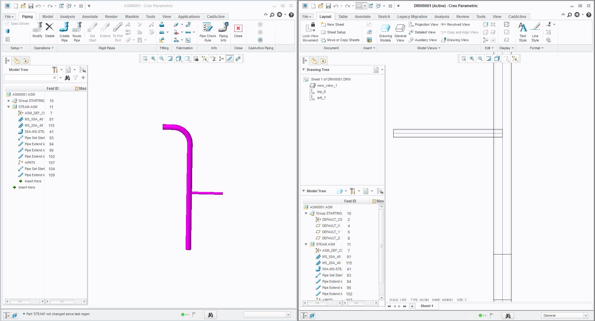
I then did a quick "Pipe Solid" to solidify my pipelines into solid geometry...
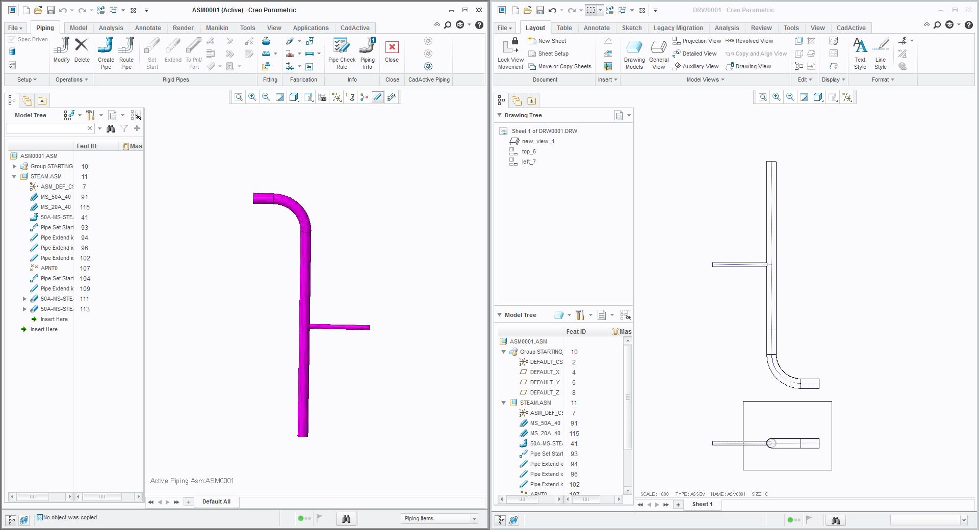
Looking closer...
When I change my view to be "hidden lines" - I get the following:
Similarly... my new "pipe solid PRT model" looks like this:
Please let me know if this is not the case on your end - I'd be more than happy to help debug.
Thanks,
James Sullivan
President & Founder
May 17, 2017
01:42 AM
- Mark as New
- Bookmark
- Subscribe
- Mute
- Subscribe to RSS Feed
- Permalink
- Notify Moderator
May 17, 2017
01:42 AM
FYI - here's my example CAD model and drawing.
Sorry my views weren't actually on the sheet - I just wanted to quickly test the graphical performance, so I didn't bother making a "real drawing" 

May 17, 2017
07:45 AM
- Mark as New
- Bookmark
- Subscribe
- Mute
- Subscribe to RSS Feed
- Permalink
- Notify Moderator
May 17, 2017
07:45 AM
James,
Thank you for this example. I don't want to speak for Anand, but this is exactly what I was hoping to see. I cannot open your models because I am on Creo 2.0, but your pictures seem to show what I want the system to do. Can you tell me why in the hidden lines view the horizontal pipe still appears to go to the centerline of the vertical pipe? Also, did Piping put a hole in the vertical pipe?
I guess I'll just have to wait until our parent company decides to upgrade everyone to Creo 3.0. Thanks again.
May 17, 2017
11:50 AM
- Mark as New
- Bookmark
- Subscribe
- Mute
- Subscribe to RSS Feed
- Permalink
- Notify Moderator
May 17, 2017
11:50 AM
Steven,
Hmm what datecode of Creo 2 are you on? I just downloaded and tested in Creo 2 M230, and it seems to perform the same way. Also... one thing to note, is that I'm using "Spec-Driven Piping" for these examples... so maybe that is the reason it isn't working? PM me and I'd be happy to download/install it to try to test it for you.
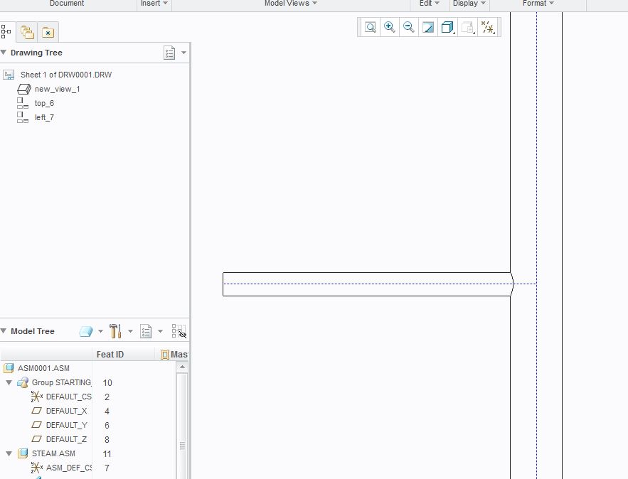
Can you tell me why in the hidden lines view the horizontal pipe still appears to go to the centerline of the vertical pipe?
I'm not quite sure why to be honest... looks to me like it still may be a bug.
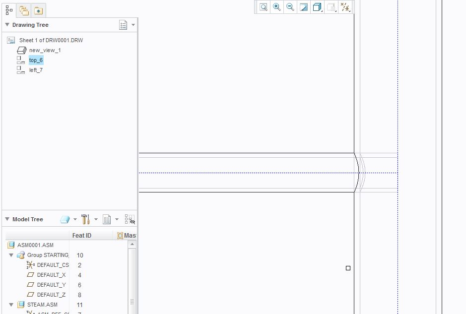
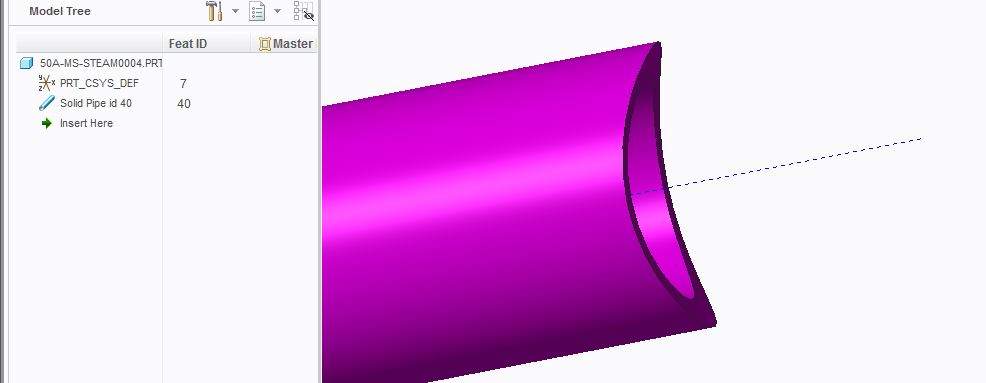
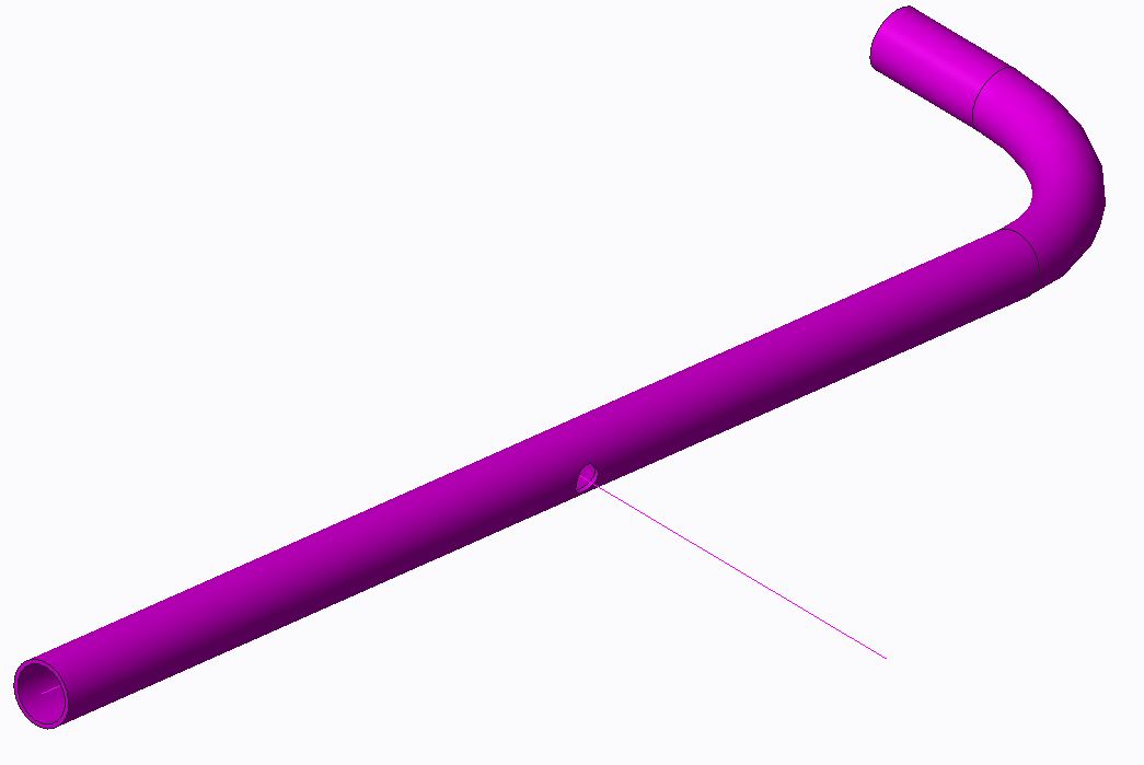
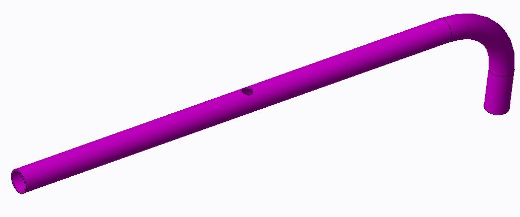
Also, did Piping put a hole in the vertical pipe?
Yep it did! You just have to make sure you turn off "thick pipes" to hide the temporary geometry... but with the pipe solid for the branch excluded... the piping assembly (first screenshot) and the pipe solid for the main trunk (second screenshot) shows as follows.
One thing to note - I did notice that it still had a bit of trouble solidifying the pipeline if the two pipes were the same size. So, it could be worth a bit more of an investigation regardless.
Also, I'd say skip Creo 3 and go directly to Creo 4 - there are a lot of other really nice features that PTC has added - especially in Piping 
Thanks,
James Sullivan
President & Founder
May 17, 2017
01:18 PM
- Mark as New
- Bookmark
- Subscribe
- Mute
- Subscribe to RSS Feed
- Permalink
- Notify Moderator
May 17, 2017
01:18 PM
Hopefully I have some big news here. I mentioned this thread to my counter part at another business unit, and he said his system copes the pipes. We are running off of the same settings, so we did some digging to figure out it. This might not be an all-inclusive solution, but we found a way to make it work every time for us, and ways that it does not work for us.
Just to tease the point, here are the ways it doesn't work first:
- Using sketches to define both pipelines. There is no trimming done on the 2nd pipe or hole in the first.
- Extruding first pipeline. Adding a datum point to it (offset from the end) to locate your second pipe, and then extruding from there. There is no trimming done on the 2nd pipe or hole in the first.
A VERY slight modification to either method is what we found works every time (for us). Create your first pipe in whatever means you find best. Doesn't matter if it is following a sketch, extruded, etc. Where you want your second pipe, Insert a straight break component (we used a tee). Doesn't matter what one, what the size is, or anything. Delete the fitting (notice it also deletes the pipe joint but leaves the datum point.) Use this datum point as the start point for your 2nd pipe.
Our only explanation is that the datum point is then associated with the pipe extrude, instead of just the pipe end, but this still seems crazy to me. Either way, it works!
Spec driven could also make the difference.
James, how are you creating your pipe segments? Would you mind testing it in one of the manors that I said didn't work (without using specs either) to see if we can replicate it?
Thank you!
May 18, 2017
12:11 AM
- Mark as New
- Bookmark
- Subscribe
- Mute
- Subscribe to RSS Feed
- Permalink
- Notify Moderator
May 18, 2017
12:11 AM
Steven,
I haven't tested creating pipes from sketches yet... but I DID see a very similar performance as you did when I added a pipe from a 2nd pipe extend (while using NON-spec-driven piping). Similarly, if I used the "pipe break" feature at all, it wouldn't seem to do what I wanted.... so I think your hypotheses could definitely be valid.
So, I think at the end of the day - it really comes down to creating "proper" branches. Spec-Driven Piping handles a lot of the branching for you automatically... so that may be why I haven't had a problem with it.
I'm finishing up preparations for LiveWorx the rest of this week (we're announcing/launching our Spec-Driven Piping configuration tool, as well as some really cool automation tools)... but I promise I'll try to test this more for you once I get back
Thanks,
James Sullivan
President & Founder
May 18, 2017
08:26 AM
- Mark as New
- Bookmark
- Subscribe
- Mute
- Subscribe to RSS Feed
- Permalink
- Notify Moderator
May 18, 2017
08:26 AM
Good to see we're at least figuring something out. I have a method I can use now, so I'm in no rush for further details.
Anand, does this information help you out?
