
Turn on suggestions
Auto-suggest helps you quickly narrow down your search results by suggesting possible matches as you type.
Showing results for
Turn on suggestions
Auto-suggest helps you quickly narrow down your search results by suggesting possible matches as you type.
Showing results for
Community Tip - You can Bookmark boards, posts or articles that you'd like to access again easily! X
- Community
- Creo+ and Creo Parametric
- 3D Part & Assembly Design
- incorrect von mises and max principal of simple li...
Options
- Subscribe to RSS Feed
- Mark Topic as New
- Mark Topic as Read
- Float this Topic for Current User
- Bookmark
- Subscribe
- Mute
- Printer Friendly Page
incorrect von mises and max principal of simple lifting lug static analysis
Aug 25, 2016
01:54 AM
- Mark as New
- Bookmark
- Subscribe
- Mute
- Subscribe to RSS Feed
- Permalink
- Notify Moderator
Aug 25, 2016
01:54 AM
incorrect von mises and max principal of simple lifting lug static analysis
Hi folks, im new here and im also new at using CREO Simulate, havent really gotten the grabs of this p-element stuff yet.
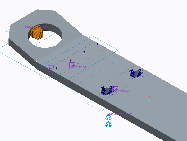
To the point: I'm performing a static analysis of a lifting lug which is affected by a force acting on a surface inside a hole, this surface models the contact surface between the hole and the lifting tool. The lifting lug is constrained by bolts in holes and i've also constrained it to only move planar for a specified surface (see picture i attached).
I set the solver to MPA where i seartch for convergence of strain energy, von mises and maximal principal stress for the whole model. I set a convergence criteria to 7%.
The current mesh setup allows the solver to find a solution within the specified convergence criteria.. BUT in the "Run status report", in the last pass, it also stated that there are X-number of elements not converged..
The result give me both von mises and max principal stresses that are WAY above the value it should be. The area of interest is the bend and the hole section, stresses at the bolt holes are not of interest. The model material is S55, ive set modulus to 190 000 MPa and poisson to 0.3.
Does anyone have a any tip or tricks to get more accurate stresses? I've also attached the .prt file so that you can try the simulation yourself.
Cheers
Labels:
- Labels:
-
Surfacing
53 REPLIES 53
Aug 25, 2016
05:37 AM
- Mark as New
- Bookmark
- Subscribe
- Mute
- Subscribe to RSS Feed
- Permalink
- Notify Moderator
Aug 25, 2016
05:55 AM
- Mark as New
- Bookmark
- Subscribe
- Mute
- Subscribe to RSS Feed
- Permalink
- Notify Moderator
Aug 25, 2016
05:55 AM
Sorry Paul but i can't see where you attached example. First time on forum aswell 
Aug 25, 2016
06:01 AM
- Mark as New
- Bookmark
- Subscribe
- Mute
- Subscribe to RSS Feed
- Permalink
- Notify Moderator
Aug 25, 2016
06:01 AM
Never mind, it just did show on my mail Or profile, had to go on the forum page. Ty Paul!
Aug 25, 2016
06:30 AM
- Mark as New
- Bookmark
- Subscribe
- Mute
- Subscribe to RSS Feed
- Permalink
- Notify Moderator
Aug 25, 2016
06:30 AM
Really nice example, and good use of symmetry. But i have a question, what if the lifting tool is applied on surface not in the top of the hole, but lets say midpoint 45 degree. How would that be then ?
Cheers
Aug 25, 2016
07:36 AM
- Mark as New
- Bookmark
- Subscribe
- Mute
- Subscribe to RSS Feed
- Permalink
- Notify Moderator
Aug 25, 2016
07:42 AM
- Mark as New
- Bookmark
- Subscribe
- Mute
- Subscribe to RSS Feed
- Permalink
- Notify Moderator
Aug 25, 2016
07:42 AM
sorry,
60 degree

Aug 25, 2016
07:44 AM
- Mark as New
- Bookmark
- Subscribe
- Mute
- Subscribe to RSS Feed
- Permalink
- Notify Moderator
Aug 25, 2016
07:44 AM
Cheers, can i ask why u didnt use the surface i created? The top of the hole. Where the lifting tool force should be applied.
Aug 25, 2016
08:06 AM
- Mark as New
- Bookmark
- Subscribe
- Mute
- Subscribe to RSS Feed
- Permalink
- Notify Moderator
Aug 25, 2016
08:22 AM
- Mark as New
- Bookmark
- Subscribe
- Mute
- Subscribe to RSS Feed
- Permalink
- Notify Moderator
Aug 25, 2016
08:22 AM
Almost there ty for taking the time to help me
The surface should be more like this
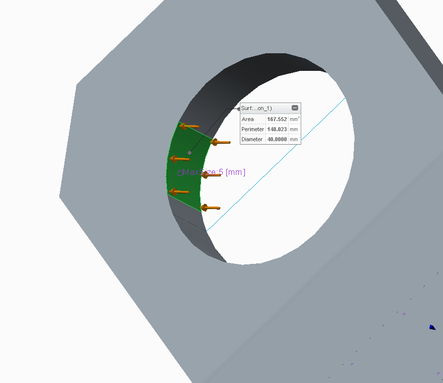
the angle from the middle of the surface to the midplane is 45 degree. The area is something i got from the lifting tool.
Also had problem running the simulation on that part you sent. It gave large deformaton issue among some.
Aug 25, 2016
11:24 AM
- Mark as New
- Bookmark
- Subscribe
- Mute
- Subscribe to RSS Feed
- Permalink
- Notify Moderator
Aug 25, 2016
11:24 AM
Hi Paul, you think you can help with that too ? simulation seem to give me high stress again, but probably because of wrong setup. Get warning regarding large deformation..
Aug 26, 2016
03:34 AM
- Mark as New
- Bookmark
- Subscribe
- Mute
- Subscribe to RSS Feed
- Permalink
- Notify Moderator
Aug 26, 2016
03:34 AM
Hi,
next step: v3 attached (without fine meshed).
Large deformation is for You not significant.
look example.
Regards
Paul
Aug 26, 2016
04:21 AM
- Mark as New
- Bookmark
- Subscribe
- Mute
- Subscribe to RSS Feed
- Permalink
- Notify Moderator
Aug 26, 2016
04:21 AM
The cylinder extrude symbolize the lifting tool i guess?
Sep 03, 2016
01:20 PM
- Mark as New
- Bookmark
- Subscribe
- Mute
- Subscribe to RSS Feed
- Permalink
- Notify Moderator
Sep 03, 2016
01:20 PM
Hi Steven,
I see, the way to achieve "real" convergence in PTC CREO simulate is quite hard. I haven't really learnt how to see if i get convergence or not, compared to H-elements.
I got some files from Paul which were very good but in his modified model the force from the lifting tool is modelled as a bearing force.. which im not really sure if thats true.. The lifting tool is a "hook" that will have a contact surface in the inner hole of ~84 mm^2. I've attached a part file which ive tried to model this more correctly but i get REALLY REALLY high stresses in the structure... the thickness and geometry of the plate should be able to handle this load according to the company.. the compoents of the force is setup to give a resultant in the direction of the sling. Please see the model
Sep 05, 2016
02:33 AM
- Mark as New
- Bookmark
- Subscribe
- Mute
- Subscribe to RSS Feed
- Permalink
- Notify Moderator
Sep 05, 2016
02:33 AM
Anyone with experiance in validation of lifting lugs / padeyes ? Maybe you can tell me how to model this correctly
Cheers
Sep 05, 2016
06:47 AM
- Mark as New
- Bookmark
- Subscribe
- Mute
- Subscribe to RSS Feed
- Permalink
- Notify Moderator
Sep 05, 2016
06:55 AM
- Mark as New
- Bookmark
- Subscribe
- Mute
- Subscribe to RSS Feed
- Permalink
- Notify Moderator
Sep 05, 2016
06:55 AM
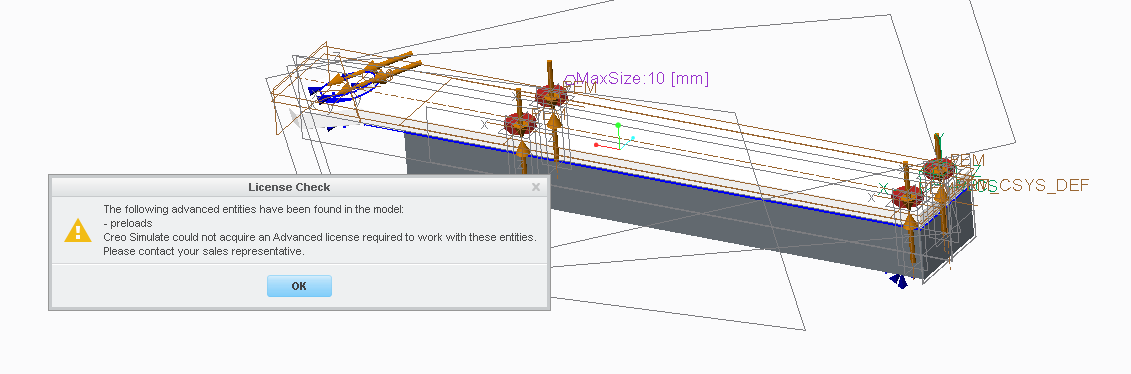
Sorry Paul but i/the company doesnt have the Advanced simulate license.
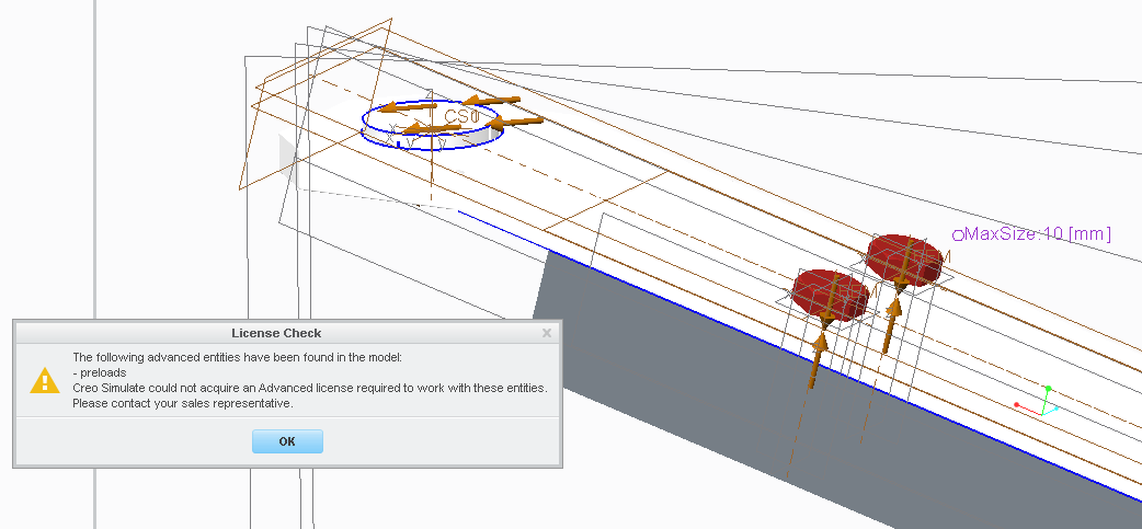
I've previously modelled using the fasterner feature instead, that i can use with the standard simulate license. I cant open that file sorry 😕
Sep 05, 2016
06:59 AM
- Mark as New
- Bookmark
- Subscribe
- Mute
- Subscribe to RSS Feed
- Permalink
- Notify Moderator
Sep 05, 2016
07:05 AM
- Mark as New
- Bookmark
- Subscribe
- Mute
- Subscribe to RSS Feed
- Permalink
- Notify Moderator
Sep 05, 2016
07:05 AM
What did you change? get the same message on that zip.
Sep 05, 2016
07:08 AM
- Mark as New
- Bookmark
- Subscribe
- Mute
- Subscribe to RSS Feed
- Permalink
- Notify Moderator
Sep 05, 2016
07:14 AM
- Mark as New
- Bookmark
- Subscribe
- Mute
- Subscribe to RSS Feed
- Permalink
- Notify Moderator
Sep 05, 2016
07:14 AM
Thank you, i can open that one. Going to see what you've done in it. Talk soon
Sep 05, 2016
07:50 AM
- Mark as New
- Bookmark
- Subscribe
- Mute
- Subscribe to RSS Feed
- Permalink
- Notify Moderator
Sep 05, 2016
07:27 AM
- Mark as New
- Bookmark
- Subscribe
- Mute
- Subscribe to RSS Feed
- Permalink
- Notify Moderator
Sep 05, 2016
07:27 AM
Okay,
I'm running the simulation now. But Paul, the cylinder in the hole you've modelled. That acts as a shackle now i guess? In this case i know that they use a specific lifting hook where the contact area of the tool and hole surface is ~thickness_of_plate*17 mm^2. This is what i tried to modell with the volume region surface, and they apply my calculated sling force on that surface. If i want the setup with lifting hook instead, how do you recommend me to do that? Also, the sling force isn't really normal to the surface in the hole, it's abit out-of-plane.
Sep 05, 2016
07:35 AM
- Mark as New
- Bookmark
- Subscribe
- Mute
- Subscribe to RSS Feed
- Permalink
- Notify Moderator
Sep 05, 2016
07:35 AM
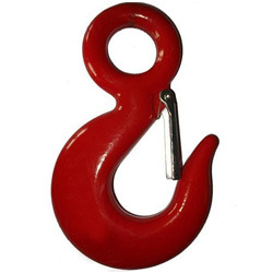
This is the type of lifting tool they use.
And this is how i've drawn the model for my analytical solutions.
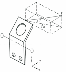
The angle "phi" is what i call sling-angle. And alpha is controlled by how the lifting lug is positioned on the structure and how the dimensions of the structure is. Lets say alpha is 71 degree, which is the worst case.
Sep 05, 2016
08:47 AM
- Mark as New
- Bookmark
- Subscribe
- Mute
- Subscribe to RSS Feed
- Permalink
- Notify Moderator
Sep 05, 2016
09:09 AM
- Mark as New
- Bookmark
- Subscribe
- Mute
- Subscribe to RSS Feed
- Permalink
- Notify Moderator
Sep 05, 2016
09:09 AM
I dont understand the angles you've defined in the coordinate system rotation ...
Sep 05, 2016
09:59 AM
- Mark as New
- Bookmark
- Subscribe
- Mute
- Subscribe to RSS Feed
- Permalink
- Notify Moderator
Sep 05, 2016
10:03 AM
- Mark as New
- Bookmark
- Subscribe
- Mute
- Subscribe to RSS Feed
- Permalink
- Notify Moderator
Sep 05, 2016
10:03 AM
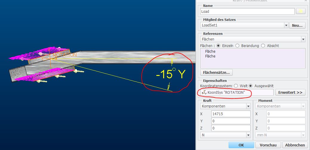
Okay, i see. Do you think i need to make a surface in the hole or should i use that cylinder you created? Then use the ROTATION coordinate system to input the force components i calculate from the phi and alpha angle ?
Sep 05, 2016
10:11 AM
- Mark as New
- Bookmark
- Subscribe
- Mute
- Subscribe to RSS Feed
- Permalink
- Notify Moderator
Sep 05, 2016
10:11 AM
the lifting tool in the hole is better
Regards
Paul
Sep 05, 2016
10:48 AM
- Mark as New
- Bookmark
- Subscribe
- Mute
- Subscribe to RSS Feed
- Permalink
- Notify Moderator
Sep 05, 2016
10:48 AM
Okay I was thinking more about that coordinate system you introduced, ROTATION. In the 2nd picture i attached, with the definition of force and angles. I could probably use the ROTATION coordinate system, but to "simplify" it more, i could rotate one of the axis to the alpha angle so that i only need to calculate two force components from the sling force. A vertical force and horisontal force.. I dont know if you've done these kind of computations before but do you think its a important factor on where the lifting tool touches the hole ? Because depending on the sling angle phi the tool will be in contact with higher or lower part of the hole. ?
Regards Robin
