
Turn on suggestions
Auto-suggest helps you quickly narrow down your search results by suggesting possible matches as you type.
Showing results for
Turn on suggestions
Auto-suggest helps you quickly narrow down your search results by suggesting possible matches as you type.
Showing results for
Community Tip - Did you know you can set a signature that will be added to all your posts? Set it here! X
- Community
- Creo Elements Direct
- Drafting
- Mechanical Simulation running speed
Options
- Subscribe to RSS Feed
- Mark Topic as New
- Mark Topic as Read
- Float this Topic for Current User
- Bookmark
- Subscribe
- Mute
- Printer Friendly Page
Mechanical Simulation running speed
Feb 06, 2017
09:56 AM
- Mark as New
- Bookmark
- Subscribe
- Mute
- Subscribe to RSS Feed
- Permalink
- Notify Moderator
Feb 06, 2017
09:56 AM
Mechanical Simulation running speed
Hello,
I have a static analysis (Creo Simulate) with nonlinear material model, large deformation. I simulate a flat bending process where the input boundary condition is the displacement of bending tool - it changes in the funcion of time.
The element number is ~ 11000 but I think, the simulation is very slow. I use win7 with 32GB RAM and 12 processors. The solver (during the calculation) use ~1.5 - 2 GB memory, and ~10% CPU. This model is a test only. The real model will include more elements, I think, and so the calculation time can be very long...
How can be increased the running speed? How can I induce the solver to use more memory and CPU%?
Thanks a lot;
Roland
Labels:
- Labels:
-
General
9 REPLIES 9
Feb 06, 2017
10:54 AM
- Mark as New
- Bookmark
- Subscribe
- Mute
- Subscribe to RSS Feed
- Permalink
- Notify Moderator
Feb 06, 2017
10:54 AM
- What value have you set for SOLRAM (the Memory Allocation parameter in the Run settings)?
- Where are your temporary and results files being written?
- What is your exact CPU model? Single-thread performance is king.
Unfortunately, you can't "make" analyses use more CPU cores - it sounds like this analysis is just using one (1/12th of 100% is about 8%, plus a couple of % for system overhead). Large linear analyses will use multiple cores for part of the solve, but it seems that many non-linear analyses cannot be parallelised.
Disk access is the main thing you can fix: put the files on a local HDD; better than that, a local SSD; or best still, a RAM drive; and allocate enough memory that it doesn't have to keep swapping blocks in and out anyway. Surprisingly, the ancient guidance of "about half your installed RAM" still holds - with a smallish model and 32GB, I'd use 8192 most of the time. However, if it's already saturating one CPU core, this is likely to make only a minimal improvement.
Feb 07, 2017
04:54 AM
- Mark as New
- Bookmark
- Subscribe
- Mute
- Subscribe to RSS Feed
- Permalink
- Notify Moderator
Feb 07, 2017
04:54 AM
Hello Jonathan,
thank you for your answer. I have a local SSD.
- SOLRAM is default. I try to set it now to 16 GB. (My RAM is 32GB). Is it OK based on your opinion?
- Temporary and result folder are same. Is it ok?
- CPU model? I dont know it. How can I set it exactly?
If the CPU % can not be increased (no parallel running) then the calculation time will not reduce significantly? But what can be the reason? I have been using ANSYS for years and in that case the using of parallel mode was possible always...
Feb 08, 2017
03:36 AM
- Mark as New
- Bookmark
- Subscribe
- Mute
- Subscribe to RSS Feed
- Permalink
- Notify Moderator
Feb 08, 2017
03:36 AM
Just to confirm, you have a local SSD and the temporary and results files are located there? Yes, I don't believe there's any problem with having them both in the same place.
16 GB SOLRAM should be plenty for that model size - like I said, 8192 (8 GB) works fine for most models, but there's no harm in going larger unless you actually start running out of RAM during the solve.
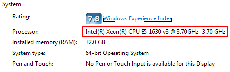
To find your CPU model, go to My Computer -> Properties, or press Win+Pause|Break. Mine, for example, is a Xeon E5-1630 v3:
There are a variety of benchmarks that compare single-thread performance (and they don't all agree on which CPUs are faster), but this one has the advantage of listing scores for the majority of CPUs:
PassMark CPU Benchmarks - Single Thread Performance
As to why a task can, or can't, be made parallel, my knowledge of programming and maths isn't sufficient to begin that discussion!
Feb 09, 2017
10:26 AM
- Mark as New
- Bookmark
- Subscribe
- Mute
- Subscribe to RSS Feed
- Permalink
- Notify Moderator
Feb 09, 2017
10:26 AM
Steven,
The locations we want accurate stresses calculated are a small proportion of the total model.
We normally have to run with a 'raw' mesh first to get a 'feel' for the behaviour
Then we home in with mesh refinements.
The rest of the model is only there to provide the correct load paths into and stiffness surrounding the location(s) of interest.
Sometimes the part/assy is too big for this 'global' model approach with mesh refinements and an increase in the amount of RAM would be welcome but ...
I have this feeling that presenting users with the ability to use much more memory then they would simply fill it with unnecessary elements rather than being efficient; the quality of FE models would not really be enhanced.
Wouldn't sub modelling be a more strategic development first?
Feb 13, 2017
04:22 AM
- Mark as New
- Bookmark
- Subscribe
- Mute
- Subscribe to RSS Feed
- Permalink
- Notify Moderator
Feb 13, 2017
04:22 AM
Hello,
thanks for your answers and ideas. I tried to increase the memory allocation to 16000MB but it has no effect on running speed. (It has a very small effect but it is not significant)
My main problem is that in the future the element number should be increased I think. The idea from Charles is very good (step 1: coarse mesh, step 2: mesh refinement based on step 1). But in the case of a complicated assambly, the mesh number will be high...about 20-30000. At the moment I have atest model including ~1000 elements. The calculation time is 2 hours. Based on it, a complicated model will run though 1-2 days. Until this moment, I used Ansys mechnanica, my computer capacity was similar. Based on my experiences, a model with 20-30000 element including nonlinear material was not problem in terms of calculation time. So I dont understand, what is the reason of long running speed in Creo mechanica?
Feb 13, 2017
08:27 AM
- Mark as New
- Bookmark
- Subscribe
- Mute
- Subscribe to RSS Feed
- Permalink
- Notify Moderator
Feb 13, 2017
08:27 AM
Roland,
An out-of-the-box install of Simulate will configure the software to use all cores.
It is possible to configure it to use fewer.
But unfortunately and as Jonathan said, non-linear studies seem only to use one core. This is the bottleneck.
My understanding is from observation rather than definitive information from those that design/code at PTC.
(fatigue advisor used only to use one core too. Fatigue calculation speed is linearly scalable by the number of cores; frustrating. I hope it's not still true).
Ansys Mechanical will use more CPU's (than the basic 2 OTB?) if you have the appropriate license. You probably had the appropriate license hence a better experience.
Ansys and Simulate have to be driven is different ways. Consider that 20-30k Simulate elements is not the same as 20-30k Ansys elements (depending of which element(s) you are using in Ansys)
A single edge in Simulate could be up to (but we try and avoid at locations of interest) 9th order and generalising, 2nd order edges in Ansys means you need more Ansys elements to describe the same shape. (over the same Simulate edge).
The implication is that you should need fewer Simulate elements to do the same job and get the same answer.
With non-linear materials, a steel that yields for example, I have found by trial and error that it is good to have 2 versions of the material. A linear and a non-linear version. With your initial fully linear study determine (by eye) the volumes that exceed yield. Create volume regions around these locations that enclose the yielding volume and are big enough to ensure the boundary of the volume is in material that has not yielded. Put your mesh refinement and non-linear properties inside these volumes.
Avoid initial interferences where the material at the interfaces is non-linear. It should work but I have had no end of trouble. (and how I discovered using volume regions to make the material at contacts linear)
Keep the mesh in the linear parts (uninteresting parts/volumes) as coarse as possible, we only care about the stiffness. Avoid abrupt changes of mesh density by nesting volume regions if required.
Assemblies, - always de-feature any components you are not interested in but don't change the stiffness too much.
It is too easy to put too many elements in.
Hope this is of use
Charles
.
Feb 16, 2017
03:22 AM
- Mark as New
- Bookmark
- Subscribe
- Mute
- Subscribe to RSS Feed
- Permalink
- Notify Moderator
Feb 16, 2017
03:22 AM
Thanks for all of you,
these are very useful informations for me. I will use it in the future.
An other question:
I simulate a sheet metal bending using non linear material of course. My first test was succesfull, I used a theoretical non linear curve. Now, I am using a measured material curve but it doesnt converge:
"Very large elasto-plastic strain calculated for your analysis. This may indicate plastic collapse.
Please review your material properties and loads, decrease the load or increase the number of load steps."
I checked the wrong result but it can be seen nothing extreme stress increasing. The stress reaches the yield...
I tried to increase the step number....and to increase the mesh density around the high stress values but it doesnt help. I know, the tangent of my material curve is very high, so a small strain means high stress changing but I have to use this curve...it is the measured curve
What do you think about it?
Thanks a lot:
Roland
Feb 16, 2017
12:10 PM
- Mark as New
- Bookmark
- Subscribe
- Mute
- Subscribe to RSS Feed
- Permalink
- Notify Moderator
Feb 16, 2017
12:10 PM
Roland,
Start linear everything.
Apply your load and review you results.
Linearly interpolate/extrapolate to determine what load/deflections you expect to reach the plastic region at the locations of interest.
Large deformation
As above but with large deformation on.
Compare results
Adjust you judgement regarding force/displacements required to get to plastic.
Now non-linear material - enforced displacement constraint
If possible apply the load by using enforced displacements.
If the load is applied using a force then there is nothing to stop a collapse if the material is unable to support the load. A constraint will not 'run away'
You can plot the reactions at the constraint to understand how the load is changing with time (distance moved by the constraint).
Remember to create measures for the constraint reactions and be careful that you do not over stiffen with the constraint.
Your linear/large def study should give you a good indication as to how much movement is required to get to the plastic region.
Create a time function accordingly
non-linear material - loads
Sometimes it is not possible to use an enforced displacement constraint.
Your initial linear/large def study should give you a good indication of the load required to get to the plastic region.
Create a time function accordingly
You have to reduce the load until it runs.
When it runs, look at you results and see what the material is doing.
If a small increase in load causes failure it could be that the load is too high and the plastic/elastic restoring force has passed its peak and further load cannot be supported.
general
If possible avoid initial interferences when using non-linear materials.
Watch the residuals decrease in the .pas file (checkpoints tab) decrease monotonically. 'oscillation' would suggest the load increment is too big, go back and refine your time steps.
Sometimes it is helpful to run a linear material buckling study to see what sort of load to expect as a maximum (given that yielding material will reduce the capacity). Though buckling studies do not permit one to use contact and so may be of limited use and contact interfaces significantly change behaviour.
Feb 20, 2017
02:47 PM
- Mark as New
- Bookmark
- Subscribe
- Mute
- Subscribe to RSS Feed
- Permalink
- Notify Moderator
Feb 20, 2017
02:47 PM
Thanks Charles!
- It was very useful. Finally I have to refine the material curve.
- You have written about the residuals. I see the residual value but can I plot the residual curve too? I could check the residual oscillation better...
- An other problem: I have a result (a temperature distribution) based on a static simulation. It will be used for a thermal expansion calcultion. I tried to define static analysis and transient analysis too. (The thermal load (in the case of transisent one) is same to the static case). Insipte of this the final maximal thermal stress is not same for both cases. What is the reason? The final temperature field is same for the static and the transient case... I think, the final stress field should be similar.... or not?
Thanks for your suggestions
Roland
Announcements
Top Tags
