
Turn on suggestions
Auto-suggest helps you quickly narrow down your search results by suggesting possible matches as you type.
Showing results for
Turn on suggestions
Auto-suggest helps you quickly narrow down your search results by suggesting possible matches as you type.
Showing results for
Community Tip - Have a PTC product question you need answered fast? Chances are someone has asked it before. Learn about the community search. X
- Community
- Creo+ and Creo Parametric
- 3D Part & Assembly Design
- Solid "Deep Drawing" (how to?)
Options
- Subscribe to RSS Feed
- Mark Topic as New
- Mark Topic as Read
- Float this Topic for Current User
- Bookmark
- Subscribe
- Mute
- Printer Friendly Page
Solid "Deep Drawing" (how to?)
Feb 25, 2014
09:41 AM
- Mark as New
- Bookmark
- Subscribe
- Mute
- Subscribe to RSS Feed
- Permalink
- Notify Moderator
Feb 25, 2014
09:41 AM
Solid "Deep Drawing" (how to?)
Hi all,
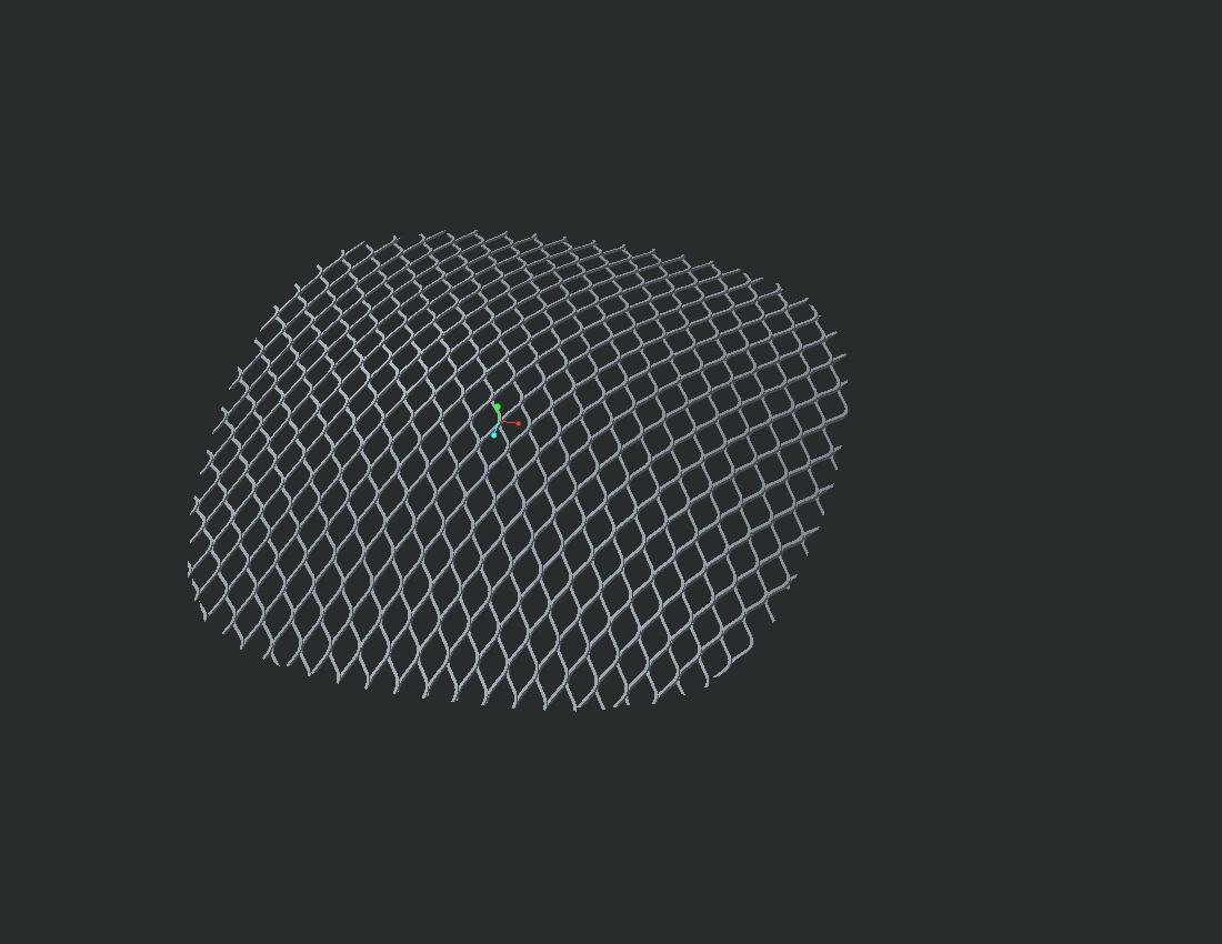
I modelled a flat "expanded metal" grid as a solid part:
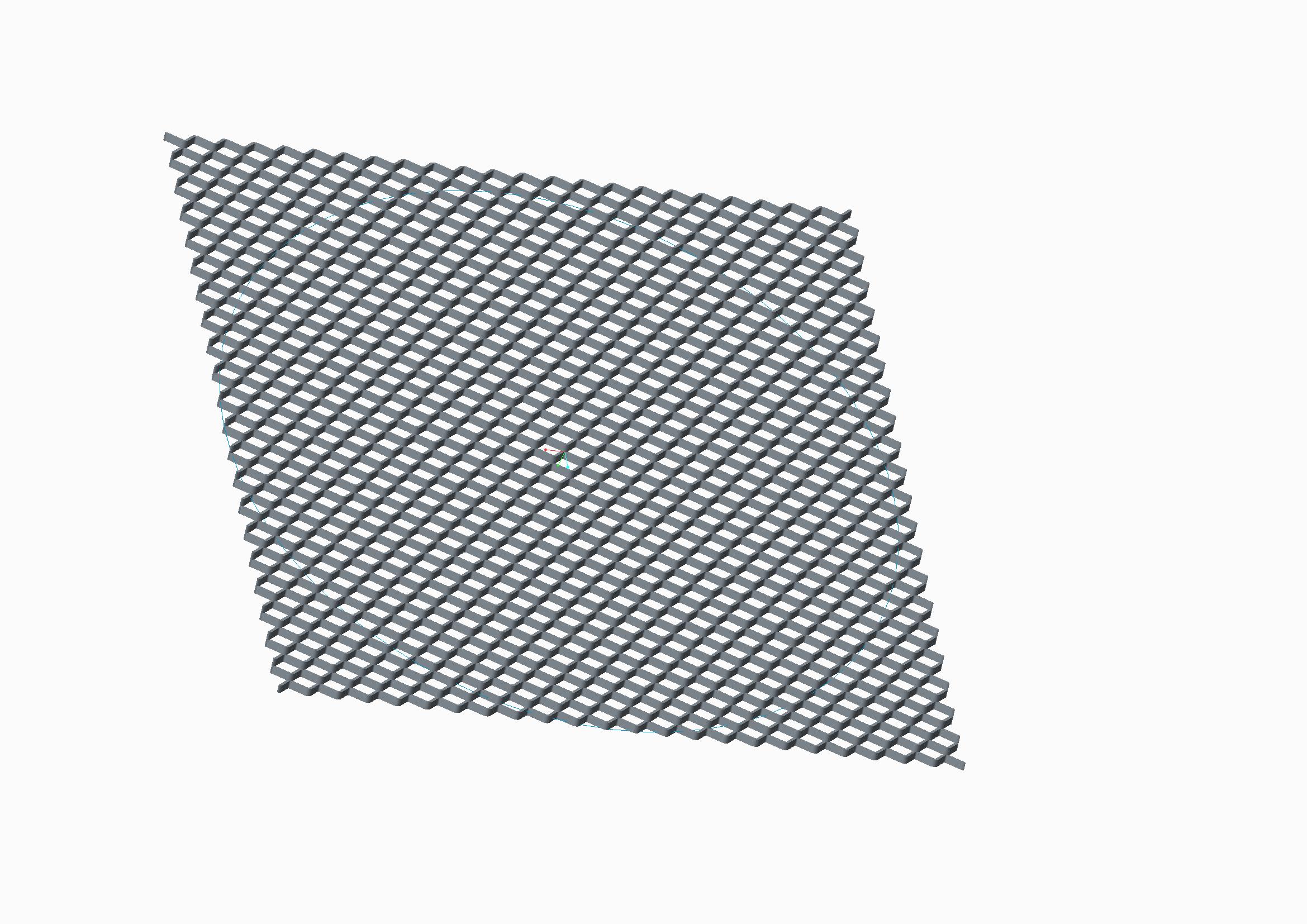
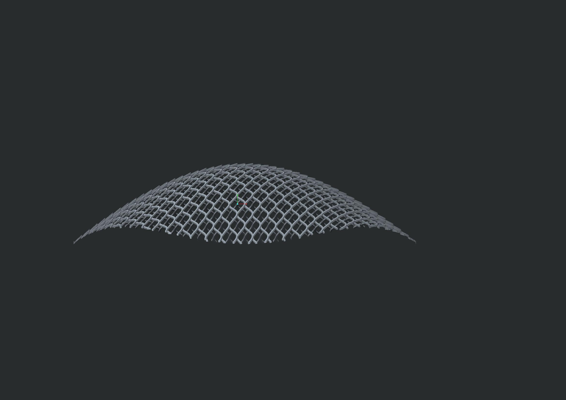
Now i would like to deep drawn it in order to give it this shape:
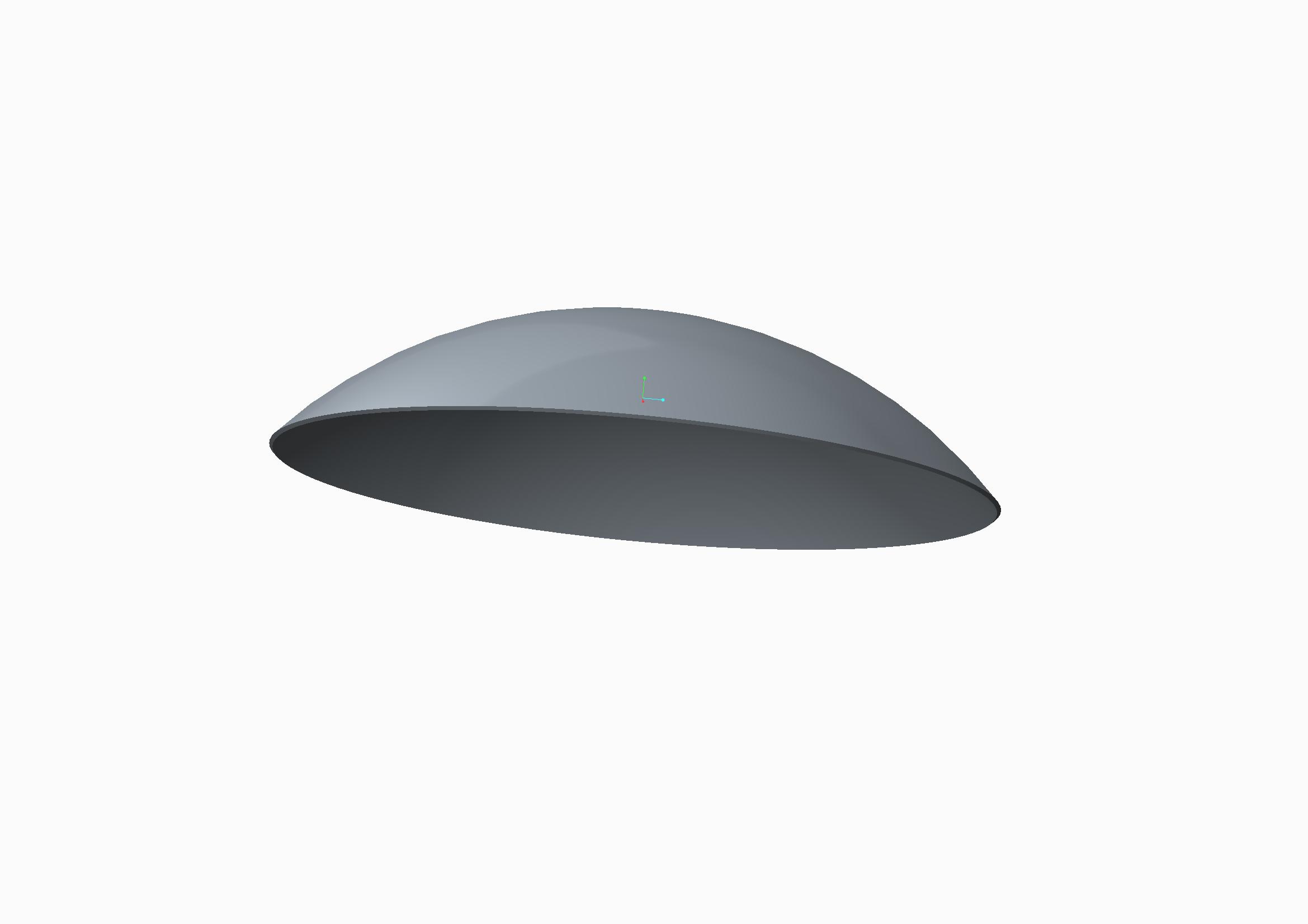
I already tryed the toroidal bend feature but I think I can only bend it around a trajectory (2D) and not deep drawn it (3D deformation).
I'm using Creo 2 Parametric
Any suggestion?
Thanks a lot
This thread is inactive and closed by the PTC Community Management Team. If you would like to provide a reply and re-open this thread, please notify the moderator and reference the thread. You may also use "Start a topic" button to ask a new question. Please be sure to include what version of the PTC product you are using so another community member knowledgeable about your version may be able to assist.
Labels:
- Labels:
-
General
40 REPLIES 40
Feb 25, 2014
01:51 PM
- Mark as New
- Bookmark
- Subscribe
- Mute
- Subscribe to RSS Feed
- Permalink
- Notify Moderator
Feb 25, 2014
01:51 PM
Welcome to the forum, davide.
You really know how to punish yourself. I don't know of any easy way to do this.
The closest I can think of to accomplish this is to creat a single cut feature and try to use a fill pattern.
This would be similar to a wire mesh screen formed into a dome.
here is a similar discussion:
Feb 25, 2014
05:52 PM
- Mark as New
- Bookmark
- Subscribe
- Mute
- Subscribe to RSS Feed
- Permalink
- Notify Moderator
Feb 25, 2014
05:52 PM
Ummm, Toroidial bend MIGHT work, but. That looks to be a different type of "expanded metal" than I've ever seen. Most are 2D, with slits pulled open. That looks slit, but formed to be a 3D shape. THAT'S gonna be the difficult part. You MIGHT try it as a sheetmetal conversion, and then run it thru a form tool. Antonius is much better at sheetmetal than I so he'd really be the one to talk to.
Feb 25, 2014
07:40 PM
- Mark as New
- Bookmark
- Subscribe
- Mute
- Subscribe to RSS Feed
- Permalink
- Notify Moderator
Feb 25, 2014
07:40 PM
Here is one similar, Frank... often used for walkway treads.

Feb 26, 2014
01:10 PM
- Mark as New
- Bookmark
- Subscribe
- Mute
- Subscribe to RSS Feed
- Permalink
- Notify Moderator
Feb 26, 2014
01:10 PM
Hmmm, that is different. Interesting. The ones I've ever looked at closely were just flat. That makes it that much more dificult......and maybe fun? 
Feb 26, 2014
06:14 AM
- Mark as New
- Bookmark
- Subscribe
- Mute
- Subscribe to RSS Feed
- Permalink
- Notify Moderator
Feb 26, 2014
06:14 AM
Thanks for your reply.
So I understand that Pro/E doesn't permit to lay (as a sheet) a solid geometry.
Regarding the suggestion to use Sheetmetal, I think it is not possible converting the original geometry because it hasn't a constant thisknes. See the image below:
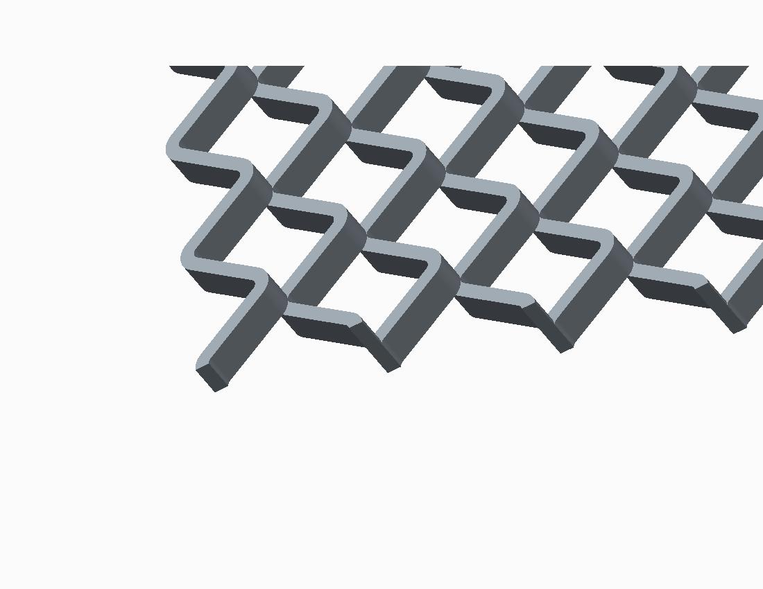
The only feature I considered to use is Flatten Quilt / Flatten Quilt Deformation, but I think I cannot warp the geometry on a spherical surface (only cilindrical..)
Feb 26, 2014
01:13 PM
- Mark as New
- Bookmark
- Subscribe
- Mute
- Subscribe to RSS Feed
- Permalink
- Notify Moderator
Feb 26, 2014
01:13 PM
Try to convert it, what do you have to lose? The sheet it's made from IS a constant thickness, and remember that sheetmetal isn't going to see thickness as you do, I think it'll see it as being constant, which, in one way (the actual material thickness), it is.
Good luck!
Feb 26, 2014
03:03 PM
- Mark as New
- Bookmark
- Subscribe
- Mute
- Subscribe to RSS Feed
- Permalink
- Notify Moderator
Feb 26, 2014
03:03 PM
In sheetmetal, you need to be able to form it in two operations.
1st, the mesh itself uses the thickness as the narrow width of the section. The VVVVVVV shape for each course is a form; stepped for the second course, and if all works out, patterned. Then you would try a dome shaped form to dome the part. Then trim the diameter.
Can sheetmetal do this? Good question.
Feb 26, 2014
03:20 PM
- Mark as New
- Bookmark
- Subscribe
- Mute
- Subscribe to RSS Feed
- Permalink
- Notify Moderator
Feb 26, 2014
03:20 PM
If there were actually numeric controls in warp you MIGHT be able to use that, But I think it'd distort the material thickness.
Feb 26, 2014
06:37 PM
- Mark as New
- Bookmark
- Subscribe
- Mute
- Subscribe to RSS Feed
- Permalink
- Notify Moderator
Feb 26, 2014
06:37 PM
You actually have to look for numerical control over some of the warp operations. However, I haven't found a dome deformation yet. I may be overlooking it.
Feb 27, 2014
02:19 AM
- Mark as New
- Bookmark
- Subscribe
- Mute
- Subscribe to RSS Feed
- Permalink
- Notify Moderator
Feb 27, 2014
02:19 AM
obviously, I already tryed to convert it in shetmetal:-)
But as you can see, the geometry is not suitable to be converted
Feb 27, 2014
02:58 AM
- Mark as New
- Bookmark
- Subscribe
- Mute
- Subscribe to RSS Feed
- Permalink
- Notify Moderator
Feb 27, 2014
02:58 AM
It certainly will not convert to sheetmetal, but you might be able to create it in sheet metal.
I am just not sure what the limitations of the form feature will be.
Feb 27, 2014
05:47 AM
- Mark as New
- Bookmark
- Subscribe
- Mute
- Subscribe to RSS Feed
- Permalink
- Notify Moderator
Feb 27, 2014
05:47 AM
I did a quick test using quilt forms and attempted to form a part not normal to the 1st form and it just ignored me.
However, I did go into the warp and was able to get a "Bulge" in a planar disk. I didn't really have any control over the shape.
Feb 27, 2014
05:12 PM
- Mark as New
- Bookmark
- Subscribe
- Mute
- Subscribe to RSS Feed
- Permalink
- Notify Moderator
Feb 27, 2014
05:12 PM
Yeah, Warp could be SO cool, if you could say: Warp this, to THIS surface. Without actual numerical controls, it's usefullness is very limited. I've gotten some great results out of it for only a few things, but I had to eyeball everything.
Feb 27, 2014
06:41 PM
- Mark as New
- Bookmark
- Subscribe
- Mute
- Subscribe to RSS Feed
- Permalink
- Notify Moderator
Feb 27, 2014
06:41 PM
Interesting... and better than I thought it could do. Not perfect because of the rectangular marque.
A bit more tweaking and you might get it darn close.
Serious CPU overhead, though!
Creo 2.0 attached. Don't be too critical of the mesh creation technique  Again, 10 iterations before one stuck.
Feb 28, 2014
01:15 AM
- Mark as New
- Bookmark
- Subscribe
- Mute
- Subscribe to RSS Feed
- Permalink
- Notify Moderator
Feb 28, 2014
01:15 AM
Nice one!
Yes, I think this is the right way.
I tryed the warp too but with bad results... i'll check your prt and I try to use the same method on my part.
thanks
Feb 28, 2014
04:26 AM
- Mark as New
- Bookmark
- Subscribe
- Mute
- Subscribe to RSS Feed
- Permalink
- Notify Moderator
Feb 28, 2014
04:26 AM
After I checked the part... yes, it is nice but it is not what I need because the edge is not flat.
This part is cutted with a cirlce from the top.
Cutting the part from the side:
the edges are ftat (on a plane) but the outline is not a cirlce.
This means that the obtained geometry is not spherical... 
Feb 28, 2014
04:57 AM
- Mark as New
- Bookmark
- Subscribe
- Mute
- Subscribe to RSS Feed
- Permalink
- Notify Moderator
Feb 28, 2014
04:57 AM
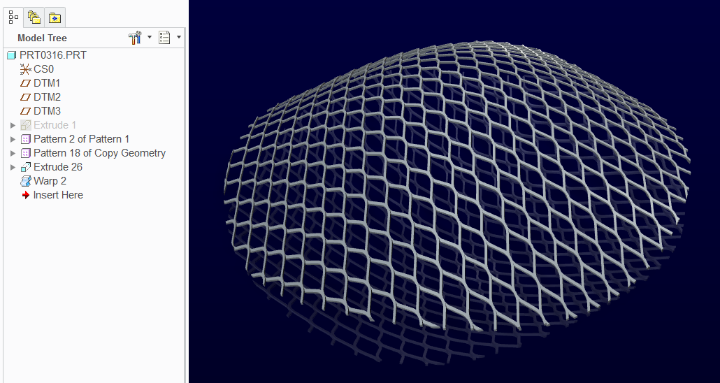
just adding a Creo part, i have used flatten quilt for this. please have a look.
Feb 28, 2014
05:36 AM
- Mark as New
- Bookmark
- Subscribe
- Mute
- Subscribe to RSS Feed
- Permalink
- Notify Moderator
Feb 28, 2014
05:36 AM
Yes,
...but try with this start geometry... (resume all features)
Feb 28, 2014
02:06 PM
- Mark as New
- Bookmark
- Subscribe
- Mute
- Subscribe to RSS Feed
- Permalink
- Notify Moderator
Feb 28, 2014
02:06 PM
Rohit, this is a really cool. I never knew what "Flatten-Quilt Deformation" did.
This is certainly worth a document. Care to create a video of exactly what this is doing?
Mar 01, 2014
01:05 AM
- Mark as New
- Bookmark
- Subscribe
- Mute
- Subscribe to RSS Feed
- Permalink
- Notify Moderator
Mar 01, 2014
01:05 AM
sure i would add the video, thanks for your appreciation.
Feb 28, 2014
05:11 AM
- Mark as New
- Bookmark
- Subscribe
- Mute
- Subscribe to RSS Feed
- Permalink
- Notify Moderator
Feb 28, 2014
05:11 AM
Right, that is what I meant about the rectangular marque. You would have to draw the corners down to "round it out".
Feb 28, 2014
02:19 PM
- Mark as New
- Bookmark
- Subscribe
- Mute
- Subscribe to RSS Feed
- Permalink
- Notify Moderator
Feb 28, 2014
02:19 PM
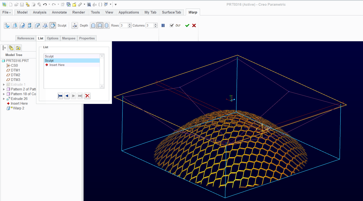
Its still not perfect but a lot closer. At least I learned that you can select all 4 corners... or center... with the Ctrl select and they move together. In this case, I added a second Sculp feature to the warp to "reset" the marque.
It takes a bit of patience but a fully accurate version is going to be difficult to accomplish.
Feb 28, 2014
02:39 PM
- Mark as New
- Bookmark
- Subscribe
- Mute
- Subscribe to RSS Feed
- Permalink
- Notify Moderator
Feb 28, 2014
02:39 PM
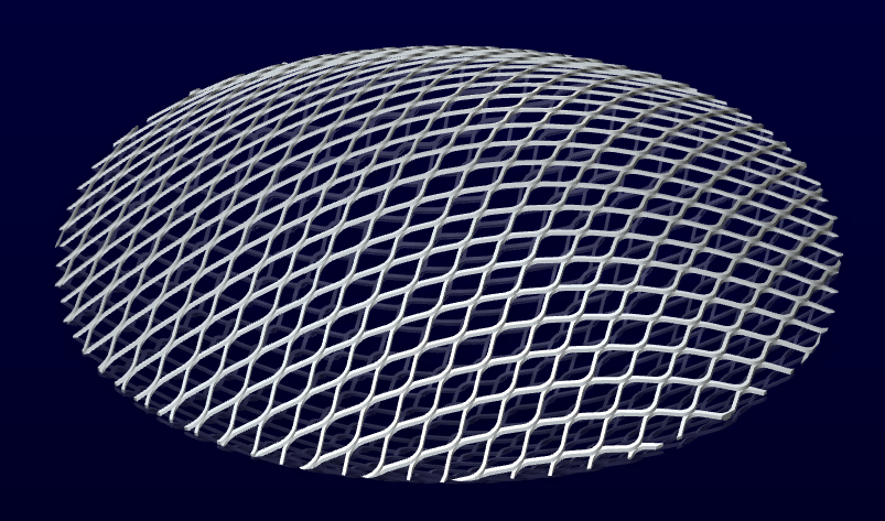
I've attached my last version... it is not a perfect dome but it is very close to an 11" diameter and 8" spherical radius.
Sculpt really needs some additional numerical control. A cylindrical marque would be very helpful too.
Maybe even direct access to a true dome algorithm is justified.
Feb 28, 2014
03:37 PM
- Mark as New
- Bookmark
- Subscribe
- Mute
- Subscribe to RSS Feed
- Permalink
- Notify Moderator
Feb 28, 2014
03:37 PM
Nice! Yeah, having played with it, I agree, there's not near enough control. Different shape marques would be nice, an dthe ability to deform TO conform to a shape (such as a spherical or boundary blend surface) or at least datum curves would be awesome. As it is, you just keep tweaking. It'd also be nice to have more control over the outcome, like if you pull on the central point, how does it deform it all the way to the edge?
Nice work though!
Mar 03, 2014
02:31 AM
- Mark as New
- Bookmark
- Subscribe
- Mute
- Subscribe to RSS Feed
- Permalink
- Notify Moderator
Mar 03, 2014
02:31 AM
This is a very nice result!
But,
at this point I'm 99% convinced that ProE has not a solution for this problem, with a good control of the final shape
and without make a very complex set of feature.
In other words, ProE cannot solve non-sheetmetal Deep Drawing.
Thanks to all
Mar 03, 2014
12:21 PM
- Mark as New
- Bookmark
- Subscribe
- Mute
- Subscribe to RSS Feed
- Permalink
- Notify Moderator
Mar 03, 2014
12:21 PM
If you want to be 100% sure, you can submit your request as a customer support case.
True, this is a real world issue that is not easily resolved in Creo Parametric.
Mar 03, 2014
12:28 PM
- Mark as New
- Bookmark
- Subscribe
- Mute
- Subscribe to RSS Feed
- Permalink
- Notify Moderator
Mar 03, 2014
12:28 PM
I think that's too broad a statement. What you're trying to do, while it may be real-world, is extremely difficult. I think it certainly COULD be done, but certainly not easily. I have a trick up my sleeve I want to try.
as fas as "edge is not flat", do you mean you want a planar lip on the model as well?
Mar 03, 2014
01:27 PM
- Mark as New
- Bookmark
- Subscribe
- Mute
- Subscribe to RSS Feed
- Permalink
- Notify Moderator
Mar 03, 2014
01:27 PM
First of all I forgot to say sorry for my english 🙂 that sometimes is not so good to explain correctly what I mean.
Anyway, i just wish that every kind of flat geometry, such as a grid, expanded metal, fabric and so on; can be formed as a sheet draped over a 3D surface (not only an half dome).
I use ProE since 1995 and I complitely satisfied, but some times I saw PTC developing non-usefull feature and ignore others that are more usefull for the real production.
I know that in this case the production requirements do not need to solve a geom like that (just a spherical half dome is ok for the mold), but it could be useful for example for a good quality rendering.
I don't know if CATIA can do it...
Mar 03, 2014
01:43 PM
- Mark as New
- Bookmark
- Subscribe
- Mute
- Subscribe to RSS Feed
- Permalink
- Notify Moderator
Mar 03, 2014
01:43 PM
There are very powerful rendering tools out there that can do amazing things with 3D geometry. These are features simply not justified in a parametric modeler like Creo. The fact that we now have a Warp feature is a boost to what Creo and PTC is capable of.
However, special tools like this typically get developed into an optional extension. Something like this might be a capability for a manufacturing tool like intelligent forming that properly predicts deformation, bunching, stretching/thinning, and other real world challenges to the metal forming industry. We will not see the product of these efforts in core Creo. People like General Motors and Boeing would pay for the development of such efforts where PTC would reserve the rights to use the resulting code for new products.
I am still wondering why toroidal bend didn't work(?)
