
Turn on suggestions
Auto-suggest helps you quickly narrow down your search results by suggesting possible matches as you type.
Showing results for
Turn on suggestions
Auto-suggest helps you quickly narrow down your search results by suggesting possible matches as you type.
Showing results for
Community Tip - Need to share some code when posting a question or reply? Make sure to use the "Insert code sample" menu option. Learn more! X
- Community
- Creo+ and Creo Parametric
- Manufacturing (CAM)
- Change lead-in radius in Rough milling
Options
- Subscribe to RSS Feed
- Mark Topic as New
- Mark Topic as Read
- Float this Topic for Current User
- Bookmark
- Subscribe
- Mute
- Printer Friendly Page
Change lead-in radius in Rough milling
Apr 23, 2015
01:42 PM
- Mark as New
- Bookmark
- Subscribe
- Mute
- Subscribe to RSS Feed
- Permalink
- Notify Moderator
Apr 23, 2015
01:42 PM
Change lead-in radius in Rough milling
Folks,
I'd like to change the lead-in radius when rough-milling. The cutter chatters because the radius is too small so I'd like to increase it. I've looked all over the place and cannot find any way to change it. Does any one know how to do this? BTW I'm on Creo 2, M100.
Ray Aviles
This thread is inactive and closed by the PTC Community Management Team. If you would like to provide a reply and re-open this thread, please notify the moderator and reference the thread. You may also use "Start a topic" button to ask a new question. Please be sure to include what version of the PTC product you are using so another community member knowledgeable about your version may be able to assist.
Labels:
- Labels:
-
General
7 REPLIES 7
Apr 24, 2015
06:51 AM
- Mark as New
- Bookmark
- Subscribe
- Mute
- Subscribe to RSS Feed
- Permalink
- Notify Moderator
Apr 24, 2015
06:51 AM
You didn't specify what type of sequence you're dealing with: volume mill, trajectory mill, etc. Makes a difference as to what parameters are needed for things.
If you are only seeing a small amount of parameters for editing, you might need to click the "All" button next to "Parameters". The lead-in radius on, for example, a trajectory milling sequence, is governed by the "LEAD_RADIUS" parameter. Also pertinent is the "ENTRY_ANGLE", which sets the portion of a full circle that the lead-in will traverse. You've really just got to play with these things to get a feel for what they do.
Apr 24, 2015
02:45 PM
- Mark as New
- Bookmark
- Subscribe
- Mute
- Subscribe to RSS Feed
- Permalink
- Notify Moderator
Apr 24, 2015
02:45 PM
Ken,
The type of sequence is "Roughing" under the Roughing ribbon button. As I mentioned earlier, I've not found any way of altering the lead in radius.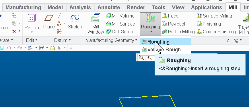
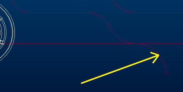
The cheap, homemade arrow points to the lead in radius in the picture below.
The roughing module works quite well for what I want to except for this problem. Somehow, I have a feeling that it's dependent on the cutter diameter. I suppose the easiest thing to do would be to use a different diameter cutter. This would work in Creo, but not in the real world because I can't use anything else to machine the feature.
Best regards,
Ray Aviles
Apr 28, 2015
10:27 AM
- Mark as New
- Bookmark
- Subscribe
- Mute
- Subscribe to RSS Feed
- Permalink
- Notify Moderator
Apr 28, 2015
10:27 AM
I have had some luck with the following options.
SMOOTH_SHARP_CORNERS - CONSTANT_RADIUS
SMOOTH_RADIUS - cutter_diam*.2
Try any and all variations for these settings if that doesn't help let me know I might have some other tricks to try.
Apr 28, 2015
01:50 PM
- Mark as New
- Bookmark
- Subscribe
- Mute
- Subscribe to RSS Feed
- Permalink
- Notify Moderator
Apr 28, 2015
01:50 PM
Nick,,
It appears that the lead-in radius depends on the STEP_OVER value. In my case, I set "STEP_OVER = CUTTER_DIAM * 0.XX" and watched the lead-in value change accordingly in the PLAY PATH dialog.
So it appears that I'm SOL unless PTC decides to make the lead-in a variable.
Thanks for your help,
Ray Aviles
Apr 29, 2015
11:03 AM
- Mark as New
- Bookmark
- Subscribe
- Mute
- Subscribe to RSS Feed
- Permalink
- Notify Moderator
Apr 29, 2015
11:03 AM
Have you tried using Volume rough with a window?
Apr 29, 2015
01:21 PM
- Mark as New
- Bookmark
- Subscribe
- Mute
- Subscribe to RSS Feed
- Permalink
- Notify Moderator
Apr 29, 2015
01:21 PM
Volume mill also has other benefits like being able to specify the entry point. It has a lot of parameters that can be adjusted to get different results. The difficult thing with them is setting up the volume, and dealing with complex geometry.
I generally use Trajectory Milling, Holemaking, and Surface Milling, and only use the other types of sequences if I have a specific need. It gives me the ability to customize motions a lot, which, of course, also allows me to screw up lots, too.
Apr 29, 2015
03:02 PM
- Mark as New
- Bookmark
- Subscribe
- Mute
- Subscribe to RSS Feed
- Permalink
- Notify Moderator
Apr 29, 2015
03:02 PM
Gents,
I have tried ROUGHING, VOLUME_ROUGH, FACE, and SURFACE_MILLING but have not had any success with it cutting like I want it to. I know that I can use CUSTOM_TRAJECTORY to do what I want, but then I have to create the toolpath manually, which defeats the purpose of having a CAM package. I've gone so far as to layout the tool path in AUTOCAD, save it as a DXF, then import the geometry into the CUSTOM_TRAJECTORY module and 'program' the toolpath like that. Unfortunately, Creo does not calculate feedrate for circular interpolation, so I use a spreadsheet to find the compensated values. In other words, it's very painful.
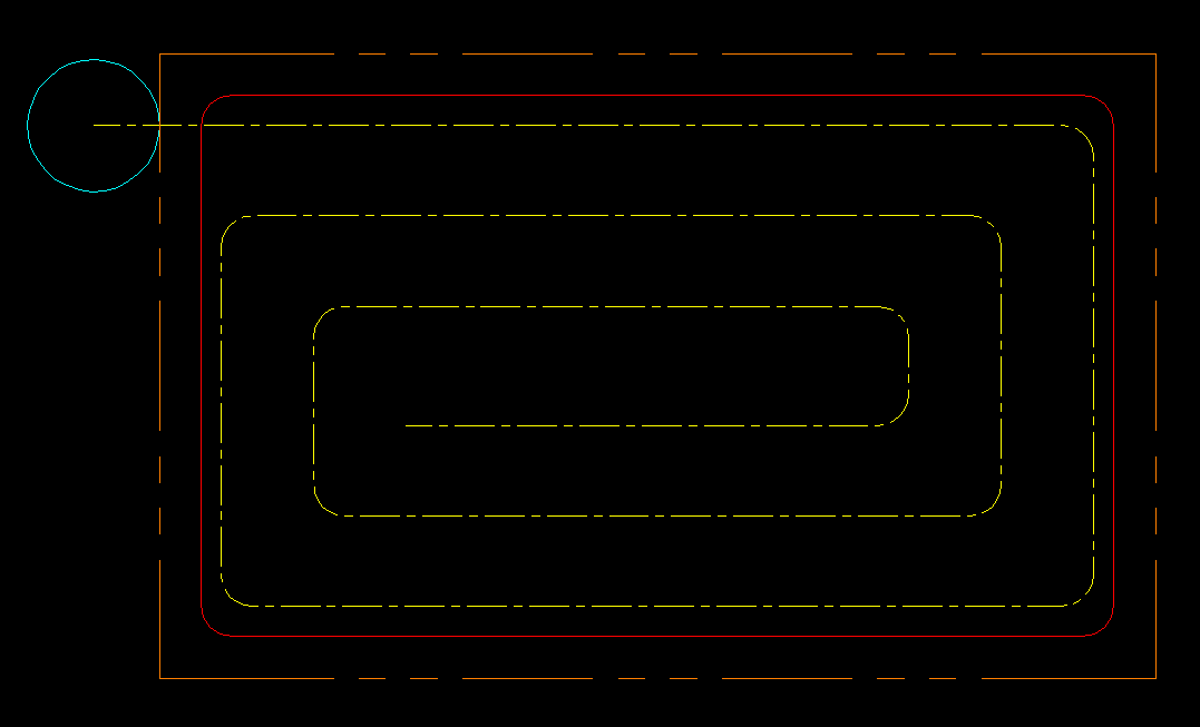
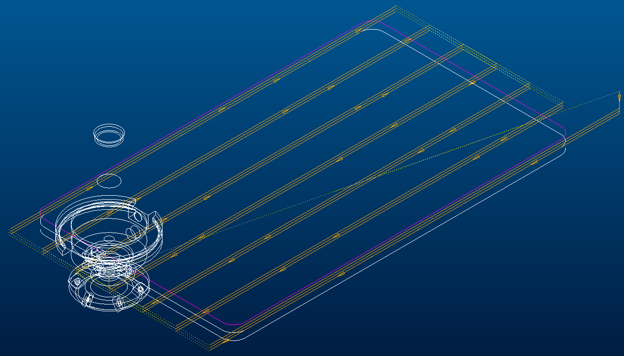
The part I'm trying to cut is a simple rounded corner rectangle, nothing complicated. The following picture shows what I want Creo to output (orange phantom = boundary, red = plate geometry, yellow centerline = toolpath). As you can see, the cutter stays in the material throughout the cut. This toolpath was manually drawn by yours truly.
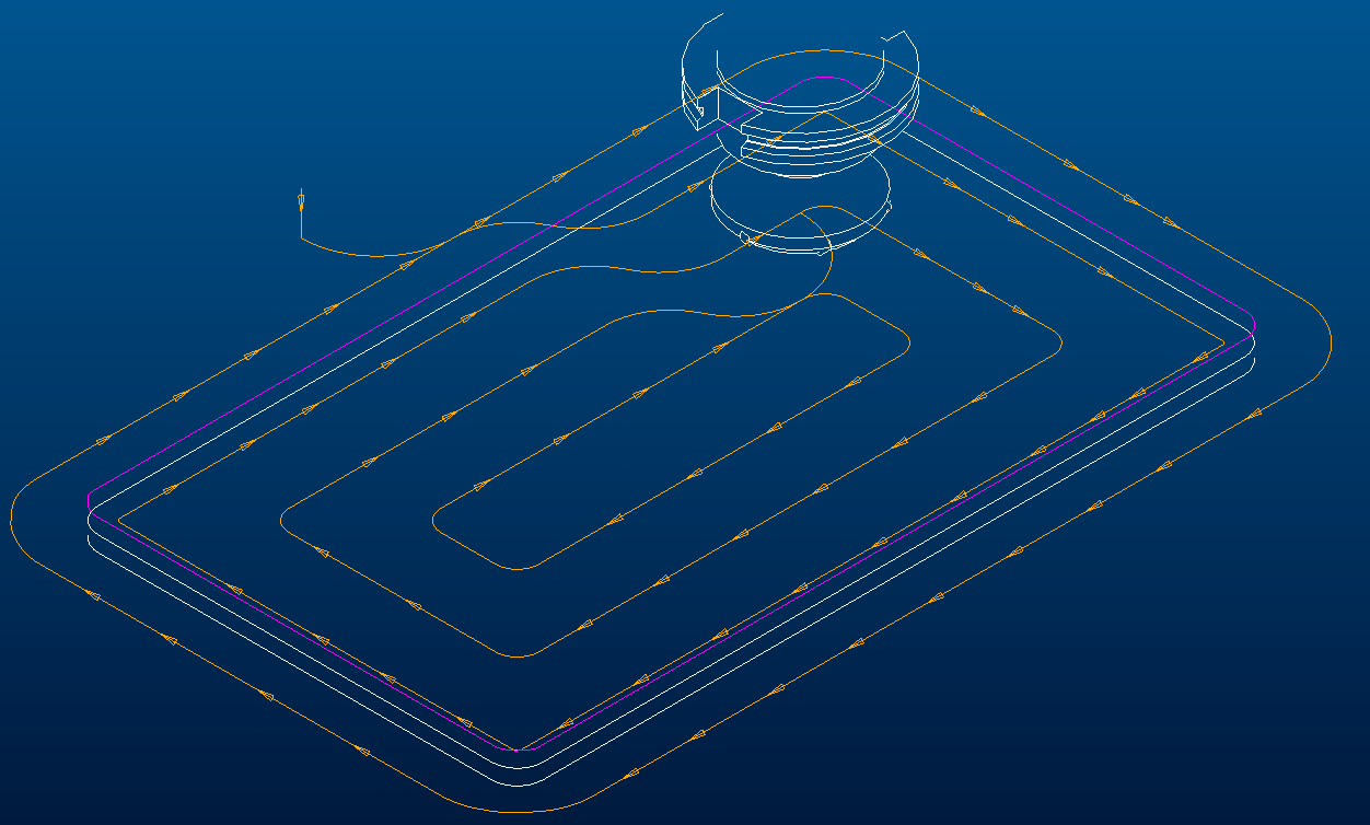
ROUGHING provides the following output, which is where the lead-in radius is fixed; it's close but no cigar.
I really though that I would find success with the FACE module, but selecting "TYPE_SPIRAL" does not keep the cutter in the material! It makes a linear cut, then rapids to the far side of the part and makes a cut. Repeat and rinse. Why can't it keep the cutter in the material?
I agree, VOLUME_ROUGHING gets me closest to what I want to do, except for the HELICAL_RAMPing that Creo insists upon. Even with all this pain, I still think that Creo is the way to go as far as which CAM package to use simply because it works with native PTC models. The company I work for has chosen another package as our officlal CAM software because of the pain experienced by many of our programmers.
I've heard that Creo MFG is absolutely outstanding when it comes to 5-axis machining; ie. molds, dies, electrodes, etc. But for simple weldment machining, it leaves a lot to be desired, so I guess that I'll keep hacking away at it.
Gotta go,
Ray Aviles
Announcements
Top Tags
