
Turn on suggestions
Auto-suggest helps you quickly narrow down your search results by suggesting possible matches as you type.
Showing results for
Turn on suggestions
Auto-suggest helps you quickly narrow down your search results by suggesting possible matches as you type.
Showing results for
Community Tip - Your Friends List is a way to easily have access to the community members that you interact with the most! X
- Community
- Creo+ and Creo Parametric
- 3D Part & Assembly Design
- How to freeze a sketch
Options
- Subscribe to RSS Feed
- Mark Topic as New
- Mark Topic as Read
- Float this Topic for Current User
- Bookmark
- Subscribe
- Mute
- Printer Friendly Page
How to freeze a sketch
Apr 29, 2015
05:34 AM
- Mark as New
- Bookmark
- Subscribe
- Mute
- Subscribe to RSS Feed
- Permalink
- Notify Moderator
Apr 29, 2015
05:34 AM
How to freeze a sketch
Hallo,
I have a problem in importing a logo in .dxf format: I would like to import it in a sketch (and then save it as .sec), but after the positioning it comes out as a multi-spline and multi point sketch. That would not a problem except for the fact that if I place it on a part to make for example an extrude (or a surface offset), I cannot move it by setting a dimension: once it is positioned, to move it I have to delete it and re-import a new one.
I already know there is the function Rotate and Resize, but this allows only rotation and relative translation (distances or contraints cannot be given).
Is there a way, somehow, to freeze the sketch so that if I move a point, the rest follows rigidly?
Here is a screenshot of my logo (forget about the open loops, that can be easily closed), if I move just one point or line of it, the global shape messes up:
![]()
Nor I can block all of its dimensions, since when I import and position the logo, some of them are related to external references.
thanks
bye
This thread is inactive and closed by the PTC Community Management Team. If you would like to provide a reply and re-open this thread, please notify the moderator and reference the thread. You may also use "Start a topic" button to ask a new question. Please be sure to include what version of the PTC product you are using so another community member knowledgeable about your version may be able to assist.
Labels:
- Labels:
-
2D Drawing
31 REPLIES 31
Apr 29, 2015
08:03 AM
- Mark as New
- Bookmark
- Subscribe
- Mute
- Subscribe to RSS Feed
- Permalink
- Notify Moderator
Apr 29, 2015
08:03 AM
First, add centerlines for the sketch origins. This will give you references to use in placement.
Second, all off your dimensions are weak and should be locked to prevent change from draging a sketch entity.
I would also suggest replacing the splines with lines, arcs and circles where possible to clean up the sketch.
There is always more to learn in Creo.
Apr 29, 2015
08:41 AM
- Mark as New
- Bookmark
- Subscribe
- Mute
- Subscribe to RSS Feed
- Permalink
- Notify Moderator
Apr 29, 2015
08:41 AM
Hi Kevin,
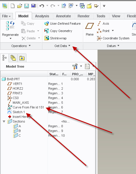
thanks for your reply. Indeed I did as you suggested, all the dimensions have been blocked and I added cenerlines, but as I wrote in the post some weak dimensions appear just after I position the imported sketch (see screenshot below) and each time I would have to block them.
![]()
Concerning your third point yes, indeed I have remade the sketch cleaning it up, I was wondering whether there was a way to freeze sketch, one never knows it happens again with another .dxf to import.
bye bye
Apr 29, 2015
09:09 AM
- Mark as New
- Bookmark
- Subscribe
- Mute
- Subscribe to RSS Feed
- Permalink
- Notify Moderator
Apr 29, 2015
09:09 AM
The added weak dimensions, most likely, are replacing dimensions to datums created when imported into CREO. Delete references to model datums, in the imported sketch before saving as .sec, to prevent this from happening. The key is to have all sketch entities locked to the centerlines in the section. Dimensions to datums are lost when saved as a section.
As far as freezing a sketch, I do not believe there is a way to freeze a sketch beyond locking all dimentions.
There is always more to learn in Creo.
Apr 29, 2015
08:16 AM
- Mark as New
- Bookmark
- Subscribe
- Mute
- Subscribe to RSS Feed
- Permalink
- Notify Moderator
Apr 29, 2015
08:16 AM
The way I handle this it to import the dxf directly in to a part file (not sketch). Then I make a sketch using the imported geometry so it can be dimensioned the way I want it and it won't have extra line segments or other unsuitable geometry. Once the new sketch is made, you can save it as a sketch for modification with the locked dimensions as Kevin suggested.
Apr 29, 2015
08:52 AM
- Mark as New
- Bookmark
- Subscribe
- Mute
- Subscribe to RSS Feed
- Permalink
- Notify Moderator
Apr 29, 2015
08:52 AM
Hi Stephen,
yes it's what I usually do, that is importing the logo directly in the part file, for instance in this case when I apply the logo as the nameplate of a product.
(In the screenshot I opened it as a skecth just to work better with the modifications and then save it).
bye
Apr 29, 2015
09:17 AM
- Mark as New
- Bookmark
- Subscribe
- Mute
- Subscribe to RSS Feed
- Permalink
- Notify Moderator
Apr 29, 2015
09:17 AM
There may be a misunderstanding. I don't import the dxf in to the sketcher. I import using GET DATA, IMPORT. That way I don't have the option to go in to sketcher for that feature. I make a new sketch feature after that using the import as reference and then break all the references and dimension the sketch as I want so I can easily reuse it by saving it as a sketch file for import into another model.
Depending on the complexity of your sketch, this may or may not be a simple task.
Apr 29, 2015
09:56 AM
- Mark as New
- Bookmark
- Subscribe
- Mute
- Subscribe to RSS Feed
- Permalink
- Notify Moderator
Apr 29, 2015
09:56 AM
ah ok, now I got it, so indeed it's similar to what is suggested here:
Solved: Import 2d dxf dwg into sketch mode without overlap... - PTC Community
(but in that case the problem was another).
Well, I tried also this way (I found that post yesterday) but by using the "Edge tool" the lines remain spline and the new sketch is practically the same as before.
(in my case, as it dipends from complexity of sketch as you say)
bye
Apr 29, 2015
09:26 AM
- Mark as New
- Bookmark
- Subscribe
- Mute
- Subscribe to RSS Feed
- Permalink
- Notify Moderator
Apr 29, 2015
09:26 AM
Not a direct answer to your question, but I've handled this in two ways.
- Import into sketcher
- Create center lines in you sketch first.
- Import your DXF into sketcher, let Creo auto dim it. I place it well off to the side to make it easy to see.
- Creo should dim the DXF all to itself with two dims to your center lines to locate it. Lock those and drag them off to the side so they don't end up on top of the import.
- Modify the locating dims to put the DXF where you want it.
- Drag a window over all the dims from the DXF to select them. Make sure your locating dims are not selected.
- Select "Modify" from the "Editing" group on the ribbon.
- In the "Modify Dimensions" dialog, select "Lock Scale"
- Now, changing any one dim will scale the entire import. Scale as you see fit, and exit.
- Import as a curve
- Using a DXF editor like Draftsight (free), scale the DXF file to the exact size that you want.
- In the editor, move the geometry in the DXF file to the right position relative to the origin. In your case I'd probably put the center of the circle at 0,0.
- Save the modified DXF.
- In Creo, Create a Coordinate system where you want the DXF origin to be. Pay attention to the orientation, i believe it'll come in on the XY plane..
- Import the DXF as a curve in the part, selecting the new CS instead of the default.
- To re-scale, you must re-edit the DXF and re-import. To move it, move the CS.
Method 1 is easier to change, but less precise. Method 2 is better if you need an exact size.
May 05, 2015
11:06 AM
- Mark as New
- Bookmark
- Subscribe
- Mute
- Subscribe to RSS Feed
- Permalink
- Notify Moderator
May 05, 2015
11:06 AM
Hi Doug,
thanks for the reply (I can reply only now for time reasons). Method 1 seems better to my needs, since I need to scale the logo according to where I will put it, and also it seems to be easier and faster.
Why do you say that it is less precise? I tried points 6-7-8 and I can set a dimension to a precise value so that in the drawings it is also dimensioned with an integer number.
Concerning instead points 1-2-3, I really can't manage to have the center lines as the only "locators" of the imported sketch. I post here below an example I made with a simple sketch and the centerlines taken both from datum ribbon, and from sketching ribbon...where am I mistakening?:
I know that what you indicate works with some sketches but only if I use these steps:
- select all the geometry by dragging a window all over the sketch
- copy (ctrl+c)
- paste it in (another) sketcher
In this way (but I repeat, not in all cases it happened to me), the only dimensioning distances were those from the centerlines of the imported sketch and those of the "hosting" sketcher.
bye bye
May 05, 2015
11:43 AM
- Mark as New
- Bookmark
- Subscribe
- Mute
- Subscribe to RSS Feed
- Permalink
- Notify Moderator
May 05, 2015
11:43 AM
My steps in method #1 above were what I use to bring the DXF into sketcher directly, not to bring in a Creo section file into sketcher. I realize this isn't what you were asking, but this is an alternate method for bringing in a logo from a DXF file.
My experience with bringing in the DXF directly has been that by creating the center lines in sketcher before importing the DXF, Creo will dimension the imported entities to themselves with a single horizontal and a single vertical dim to the center-lines. I can't say that it will always do so, just that it has in my experience.
I call this "less precise" compared to my second method because I drag the logo entities to the approximate size that I want visually rather than scaling the DXF to the exact size I want.
I hope that clears it up.
May 07, 2015
05:03 AM
- Mark as New
- Bookmark
- Subscribe
- Mute
- Subscribe to RSS Feed
- Permalink
- Notify Moderator
May 07, 2015
05:03 AM
yes I knew you were refering to the dxf import (and not to the sketch as I did), but the problem of importing a dxf is, as you said, that it doesn't have inside a fixed reference system to which I can set distances with respect to the coordinate system of the hosting sketcher...but only drag and position it. So I tried directly by saving the imported dxf as a .sec because I knew that as a .sec there is some way (but, as the screen recording video shows, how?  ) to set the distance between this
  and the centerlines of the hosting sketcher.
bye
May 05, 2015
12:06 PM
- Mark as New
- Bookmark
- Subscribe
- Mute
- Subscribe to RSS Feed
- Permalink
- Notify Moderator
May 05, 2015
12:06 PM
When importing the section into the sketch CREO seems to randomly place dimensions to fully constrain the sketch. Just add dimensions to the center lines and the weak dimensions CREO added will be deleated.
The precision when scalling is in rounding of dimensions to the default decimal places.
Also, I have set the option sketcher_lock_modified_dims to yes to automatically lock dimensions as they are modified. This keeps dimension I have set from being replaced when new dimensions are added and from changing when entities are dragged.
There is always more to learn in Creo.
May 07, 2015
05:15 AM
- Mark as New
- Bookmark
- Subscribe
- Mute
- Subscribe to RSS Feed
- Permalink
- Notify Moderator
May 07, 2015
05:15 AM
Ok now I got what you meant regarding the centerlines, I tried and the positioning seems to be working, with no resulting weak dimensions: but, this is valid just with the .sec sketch I saved from the imported .dxf (as the screen recording shows).
Instead, returning to the dxf importing, if I try to lock all dimensions (and constraints) of the imported .dxf, except for the distances I want to set, -> and then I change these, the resulting form is still messed up -> (that's why I talked about freezing the geometry)
May 07, 2015
08:24 AM
- Mark as New
- Bookmark
- Subscribe
- Mute
- Subscribe to RSS Feed
- Permalink
- Notify Moderator
May 07, 2015
08:24 AM
Place the dxf away from the sketcher references, create centerlines in the imported dxf, remove all sketcher references (this breaks all references to entities outside the sketch), make all constraints strong and lock all dimensions, select new sketcher references, and add dimensions to the centerlines. You can now move it around.
There is always more to learn in Creo.
Apr 29, 2015
09:51 AM
- Mark as New
- Bookmark
- Subscribe
- Mute
- Subscribe to RSS Feed
- Permalink
- Notify Moderator
Apr 29, 2015
09:51 AM
For what it's worth, in Creo Parametric 2.0, cosmetic sketches can be underconstrained:
Enhancement Details: Cosmetic Sketch Enhancements - PTC.com
In Cosmetic Sketch you can turn off the sketcher solver by clicking Setup and then selecting the Under-Constrained Mode checkbox.
No dimensions are displayed in under-constrained mode. Sure wish this worked on sketched curves as well.
May 05, 2015
11:13 AM
- Mark as New
- Bookmark
- Subscribe
- Mute
- Subscribe to RSS Feed
- Permalink
- Notify Moderator
May 05, 2015
11:13 AM
Hi JLG,
thanks for your reply, interesting that function, I didn't know about it. One can also move the imported sketch and set distances of one (or more) of its points in order to locate it in a parametric way?
bye
Apr 29, 2015
10:53 AM
- Mark as New
- Bookmark
- Subscribe
- Mute
- Subscribe to RSS Feed
- Permalink
- Notify Moderator
Apr 29, 2015
10:53 AM
What about this workflow:
1) Place a datum point on the surface where you will place your logo.
2) Starting a sketch on that surface.
3) When selecting references, delete any auto-selected ones and use only the datum point you created above.
4) Import your DXF data. Everything is auto-dimensioned to this datum point reference.
Done!
Now move the datum point if you need to reposition your logo...
May 05, 2015
11:24 AM
- Mark as New
- Bookmark
- Subscribe
- Mute
- Subscribe to RSS Feed
- Permalink
- Notify Moderator
May 05, 2015
11:24 AM
Hi Paul,
the problem isn't much the references but how to lock the geometry indeed, and then to create 2 axes (or a point also) to locate the sketch. If I use your way, the problem of locating the sketch with respect to the point still remains (I have just posted a video to Doug with the problem of centerlines)
bye
Apr 29, 2015
11:08 AM
- Mark as New
- Bookmark
- Subscribe
- Mute
- Subscribe to RSS Feed
- Permalink
- Notify Moderator
Apr 29, 2015
11:08 AM
I don't have a direct answer to your question, but we handle this problem a different way.
Import your geometry into a FONT creation utility. Create a TrueType font, then use this font in Creo to make your features.
May 07, 2015
03:16 AM
- Mark as New
- Bookmark
- Subscribe
- Mute
- Subscribe to RSS Feed
- Permalink
- Notify Moderator
May 07, 2015
03:16 AM
Hi Wayne,
is there a reason why you suggest to use a font? and is there a specific program utility you suggest?
thanks
bye
Apr 29, 2015
05:23 PM
- Mark as New
- Bookmark
- Subscribe
- Mute
- Subscribe to RSS Feed
- Permalink
- Notify Moderator
Apr 29, 2015
05:23 PM
Usually with logos I will create another part with the logo cleaned up and import into the part to use.
Create a part to work with the logo and import the DXF file into the sketcher and save the sketch as is. Use this sketch as a template and start recreating the logo with multiple other sketches to keep each sketch simple. Use edge (project - in creo) where you can and recreate spines with arcs or conics if needed and break down the logo into simpler shapes (ie: each letter at a time). Once you have all the logo recreated publish geometry of the curves that make up the logo. Before you create the published geometry create other curves and datum planes and coordinated systems to help locate the logo in a desired part.
Use this as an original for copying later for many other parts. For each application make a copy of the logo file and scale the part as needed in the new part. This will also help keep your target part simpler. This will also make it easier and consistent to implement into other parts. Like with most logos or special text the DXF or DWG imported files will have tons of lines, segments missing, crazy splines, etc. which will need to be cleaned up anyway. This method can be tedious, but well worth it on the long run to recreate these line arts in another part and import.
Bottom line is don't try to mess with the original and "freeze sketch", but keep as is and use it as a template to recreate accurately and cleanly.
May 07, 2015
03:20 AM
- Mark as New
- Bookmark
- Subscribe
- Mute
- Subscribe to RSS Feed
- Permalink
- Notify Moderator
May 07, 2015
03:20 AM
Hi Mark,
I didn't understand very much your indications, in particular when you say "Use this sketch as a template and start recreating the logo with multiple other sketches to keep each sketch simple". And also, what is "published geometry"?.
(maybe with a screen recording if it's not too much bothering would be clearer)
thanks
bye
May 13, 2015
10:59 AM
- Mark as New
- Bookmark
- Subscribe
- Mute
- Subscribe to RSS Feed
- Permalink
- Notify Moderator
May 13, 2015
10:59 AM
tleati,
The idea is to bring in the sketch as is and save it. Then create other sketches using the original as a guide to draw over top of or possible use the same line segments. In general it is best to keep sketches simple in Creo, so thus the problem with logos and other line art imported files that have tons of dimensions. Recreate the logo or line art in numerous sketches so each is simple like each sketch might be a separate letter. Once you have all the parts of the logo or line art created in multiple sketches you can select the line segments as needed in an offset or extrude feature.
Better yet is to share the geometry with other part with Publish Geometry feature. You might need an Advance Assembly module to get this functionality. It is a 'canned' way to define geometry, curves, datums, etc from one part to use in others. In the other part you use Copy Geometry and assemble the part in a desire location and then can use those surfaces, curves, datums, etc in a related part. In this case creating a logo in a main part to same in a library and then reuse the logo in many of parts without having to recreate it every time.
Mark Peterson
May 06, 2015
10:11 AM
- Mark as New
- Bookmark
- Subscribe
- Mute
- Subscribe to RSS Feed
- Permalink
- Notify Moderator
May 06, 2015
10:11 AM
Can´t insert video directly here.
Please see Video Link : 6037
It´s shows my expierences with similar problem and it works fine for me.
May 07, 2015
03:52 AM
- Mark as New
- Bookmark
- Subscribe
- Mute
- Subscribe to RSS Feed
- Permalink
- Notify Moderator
May 07, 2015
03:52 AM
Hi Milan,
thanks very much for your video, it's a way I could use, I will give a try in my case and let you know. The "freezing" option of my first post was indeed to lock all the dimensions of the imported sketch with a single command.
I have two questions on your video:
- how can I save my sketch as a logo and find it in the palette?
- my problem is also the coordinate system in the imported sketch: I cannot manage to add a coordinate reference system to which dimensions are taken (see video in my reply to Doug Schaefer) and also to move the center (![]() ) with respect to the sketch and locate it in a specific point of the sketch.
) with respect to the sketch and locate it in a specific point of the sketch.
thanks
bye
Tommaso
May 07, 2015
06:29 AM
- Mark as New
- Bookmark
- Subscribe
- Mute
- Subscribe to RSS Feed
- Permalink
- Notify Moderator
May 07, 2015
06:29 AM
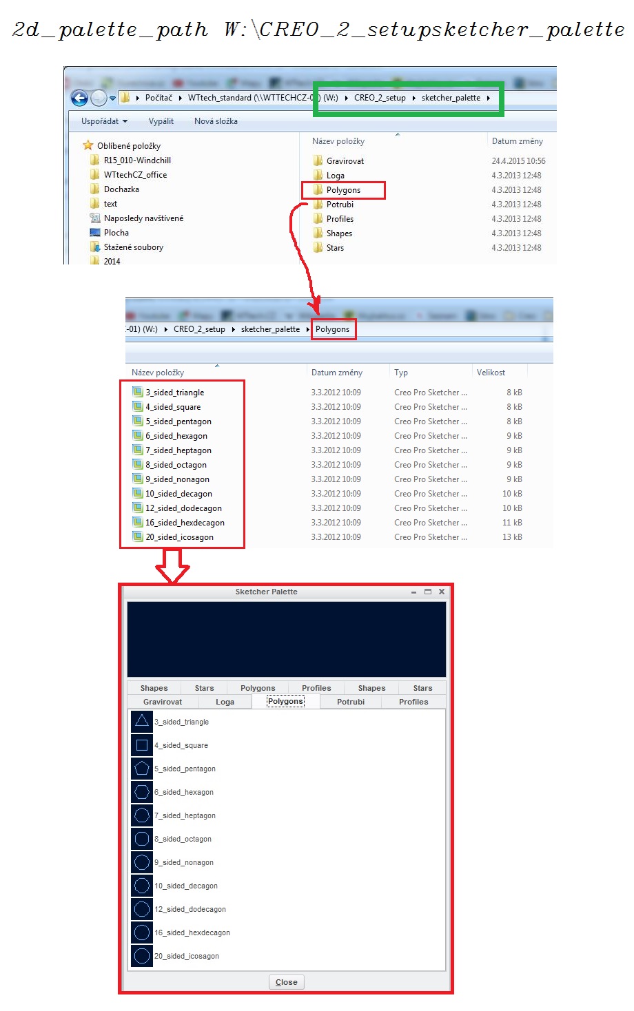
l got my logo sketch from DXF file. Don´t remember exactly how l create my logo from DXF.
Once you got your sketch use SAVE AS INSIDE SKETCHER MODE ---> Creo will ask you to save a *.sec file ---> it´s a sketch, that you can put in your sketcher palette.
Set your config options 2d_palette_path. In my case full path is: 2d_palette_path W:\CREO_2_setup\sketcher_palette
You can make a folder structure als you wish.
Have no answer for your second question 
May 07, 2015
12:38 PM
- Mark as New
- Bookmark
- Subscribe
- Mute
- Subscribe to RSS Feed
- Permalink
- Notify Moderator
May 07, 2015
12:38 PM
For logo's, this is what I did with our company logo. Not, it comes in more like an AutoCAD "block", and the whole thing scales easily and equally. As soon as you insert it, however, you're stuck, and must delete and then add it again if you want to scale it all easily. Pro/E REALLY needs "block" functionality for this kind of stuff.
May 13, 2015
11:59 AM
- Mark as New
- Bookmark
- Subscribe
- Mute
- Subscribe to RSS Feed
- Permalink
- Notify Moderator
May 13, 2015
11:59 AM
Blocks are symbols... which can easily be scaled within the dialog during creation or after the fact.
May 20, 2015
07:21 PM
- Mark as New
- Bookmark
- Subscribe
- Mute
- Subscribe to RSS Feed
- Permalink
- Notify Moderator
May 20, 2015
07:21 PM
...in the drawing, but can they also when you insert them into a sketch besides just the first time? To freely be able to move it as an unimensioned block and scale it whenever desired? Now THAT would be an enhancement!
