
Turn on suggestions
Auto-suggest helps you quickly narrow down your search results by suggesting possible matches as you type.
Showing results for
Please log in to access translation
Turn on suggestions
Auto-suggest helps you quickly narrow down your search results by suggesting possible matches as you type.
Showing results for
The PTC Community is on temporary read only status in preparation for moving our community to a new platform. Learn more here
- Community
- Creo+ and Creo Parametric
- 3D Part & Assembly Design
- 0 mm rip pattern
Translate the entire conversation x
Please log in to access translation
Options
- Subscribe to RSS Feed
- Mark Topic as New
- Mark Topic as Read
- Float this Topic for Current User
- Bookmark
- Subscribe
- Mute
- Printer Friendly Page
0 mm rip pattern
Feb 16, 2015
12:20 PM
- Mark as New
- Bookmark
- Subscribe
- Mute
- Subscribe to RSS Feed
- Permalink
- Notify Moderator
Please log in to access translation
Feb 16, 2015
12:20 PM
0 mm rip pattern
Hello
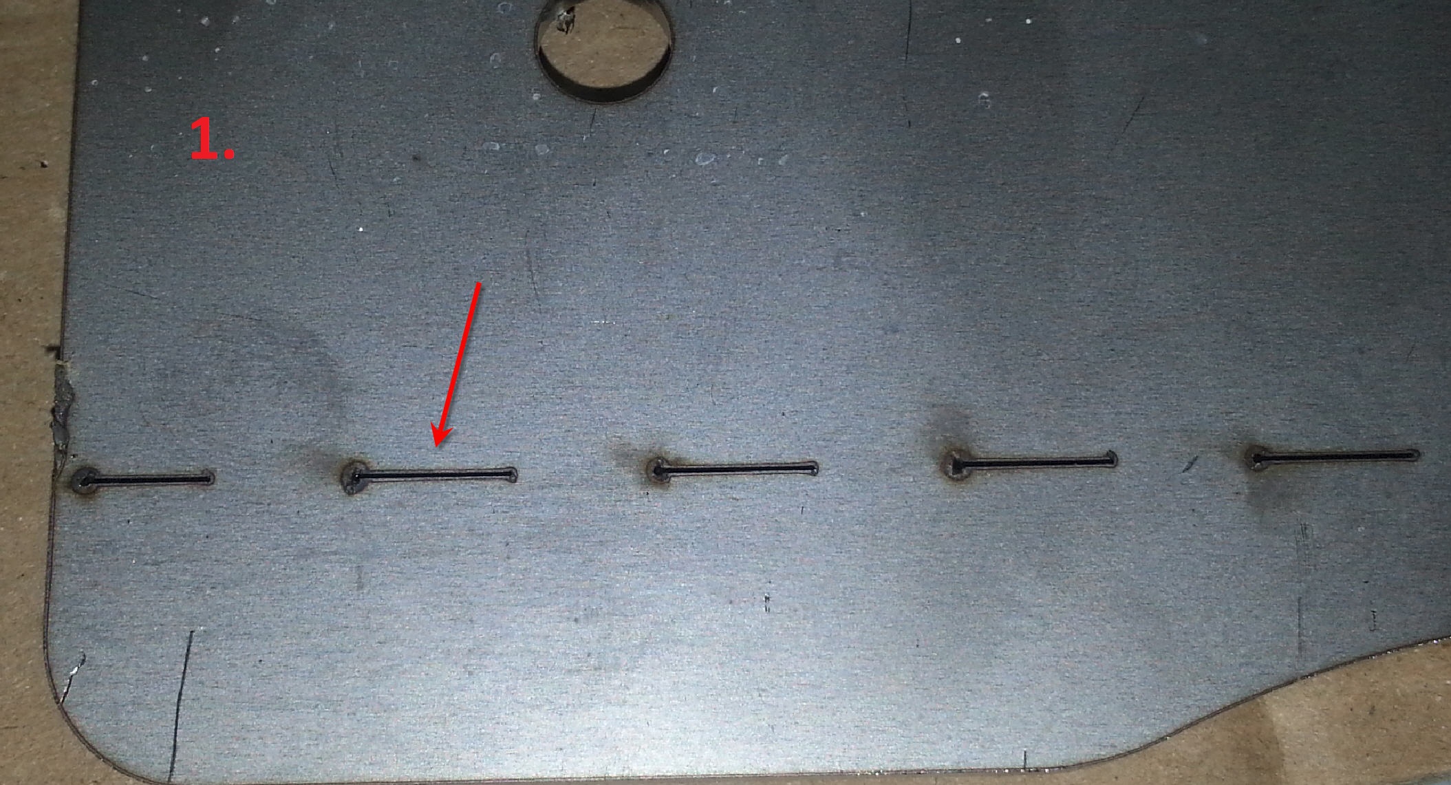
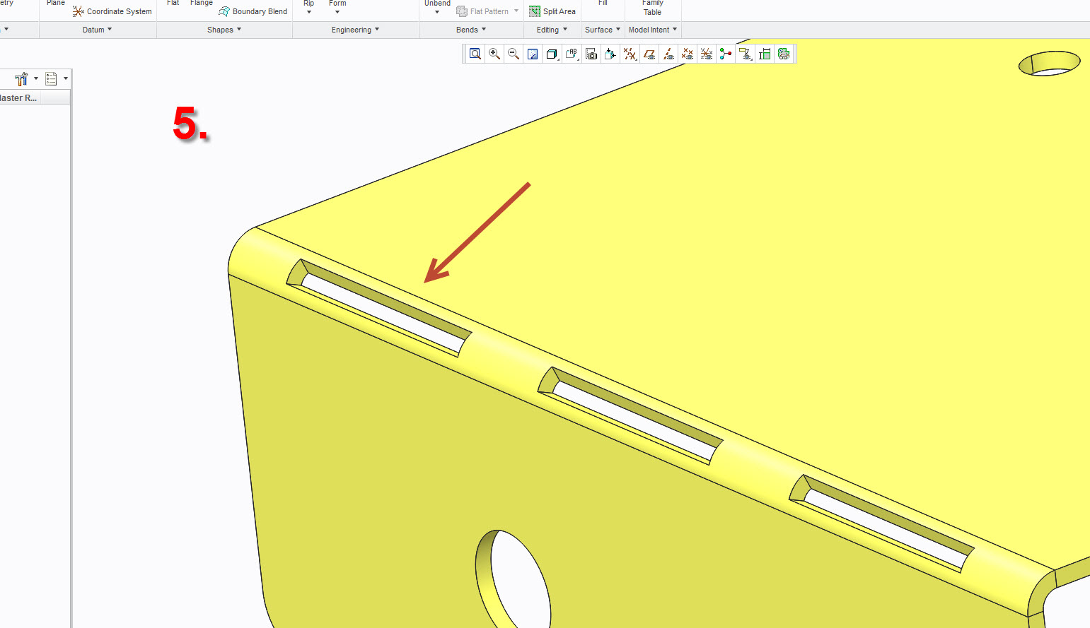
I have a little problem with sheet metal module in Creo 2. I want to make rip on a bent edge with 0 thickness so when i would unfold the plate i should get pattern of only 1 line for laser cutting procedure. I need those rips for hand bending as you can see from pictures:
I want to reduce the laser cutting time, so instead of those rectangles (picture3) i want to get pattern of lines (pic1)
To get these lines i had to send those dxf to a friend so he could delete those rectangles and put lines instead. He used some other program to do that.
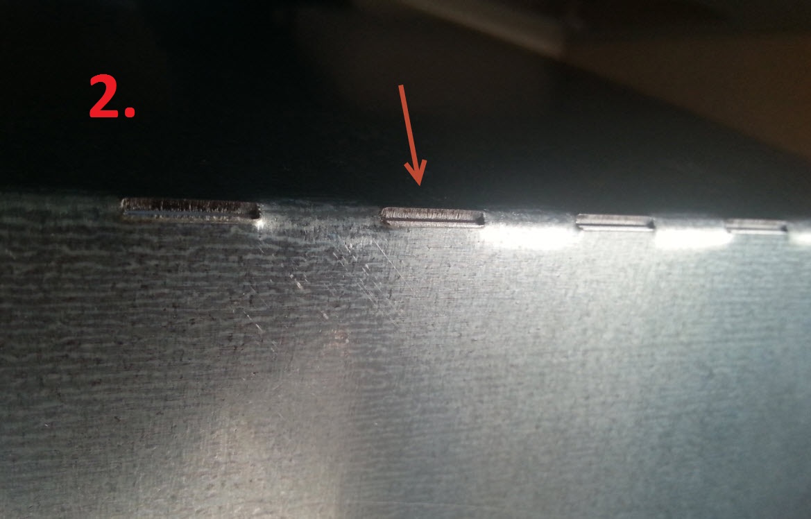
pic 1 & 2 lines
Dxf with rectangles costs 2x more because of longer cutting time 
And i received this:
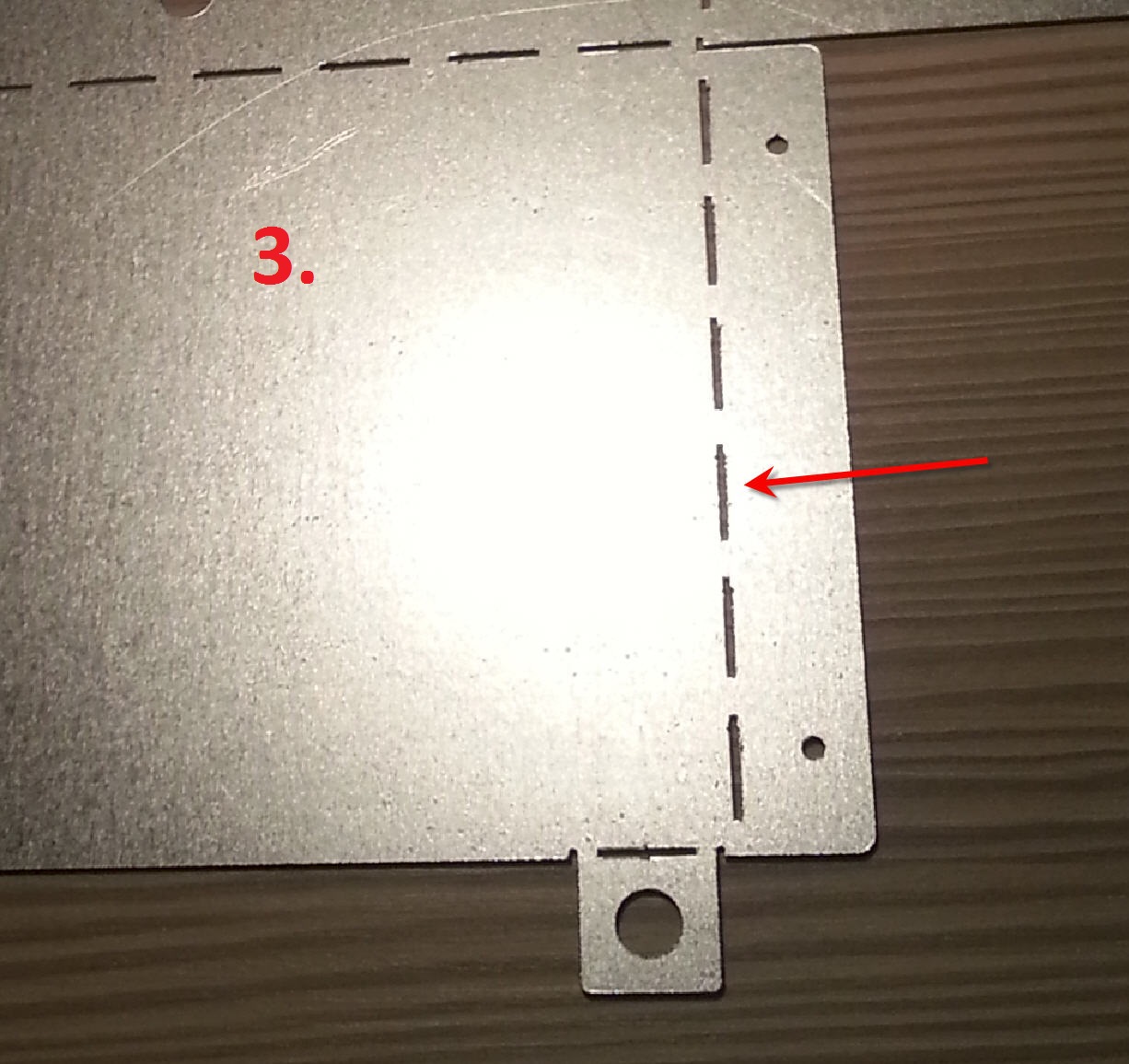
pic 3 & 4 rectangles
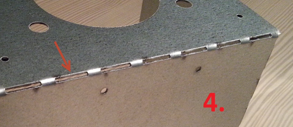
All those parts can be bent by hand.
I placed a plane on 2 side edges and extrude rectangle shape like seen in next picture:
I can draw lines on drawing or on a sketch but this would take me to much time and its not attached to flat state after doing some changes 
Is there any way to put rip in the middle of this bent edge and make pattern of it ?
Regards Andraz
This thread is inactive and closed by the PTC Community Management Team. If you would like to provide a reply and re-open this thread, please notify the moderator and reference the thread. You may also use "Start a topic" button to ask a new question. Please be sure to include what version of the PTC product you are using so another community member knowledgeable about your version may be able to assist.
Solved! Go to Solution.
Labels:
- Labels:
-
General
ACCEPTED SOLUTION
Accepted Solutions
Feb 16, 2015
01:55 PM
- Mark as New
- Bookmark
- Subscribe
- Mute
- Subscribe to RSS Feed
- Permalink
- Notify Moderator
Please log in to access translation
Feb 16, 2015
01:55 PM
Use projected curves onto the flat to get the lines to follow the surface bending/unbending.
I think there isn't a way for the software to manage a slot that has no sides. A rip doesn't exist in a real flat pattern, so it doesn't have sides, but the software can't display it that way. I expect that software that appears to do this only does it by adding the location of the rip to the flat pattern as a curve, not a solid feature.
2 REPLIES 2
Feb 16, 2015
01:55 PM
- Mark as New
- Bookmark
- Subscribe
- Mute
- Subscribe to RSS Feed
- Permalink
- Notify Moderator
Please log in to access translation
Feb 16, 2015
01:55 PM
Use projected curves onto the flat to get the lines to follow the surface bending/unbending.
I think there isn't a way for the software to manage a slot that has no sides. A rip doesn't exist in a real flat pattern, so it doesn't have sides, but the software can't display it that way. I expect that software that appears to do this only does it by adding the location of the rip to the flat pattern as a curve, not a solid feature.
Feb 16, 2015
02:21 PM
- Mark as New
- Bookmark
- Subscribe
- Mute
- Subscribe to RSS Feed
- Permalink
- Notify Moderator
Please log in to access translation
Feb 16, 2015
02:21 PM
Thanks a lot! Projected curve is good idea.
Have a great day !


